A star-delta starter wiring diagram uses three contactors and one timer relay to start a three-phase motor in star (Y), which cuts the starting current to about one third, and then, after a few seconds, switches it to delta (Δ) to run at full power: the main contactor K1 feeds U1, V1 and W1; the star contactor K2 shorts U2, V2 and W2 together; the delta contactor K3 connects U2, V2 and W2 back to the supply; the timer decides when K2 drops out and K3 pulls in, and an interlock makes sure K2 and K3 can never close at the same time. The essential condition is that the motor must run in delta at the actual supply voltage, so its nameplate must read Δ 380V (or 400V). This lesson goes from the motor terminal box through the power circuit, the control circuit and timer setting to a worked example of a 15 kW pump motor with every component sized.
By the end of this lesson, you will be able to:
- Read a motor nameplate and decide whether that motor can be star-delta started on a 380V supply.
- Draw and wire the three-contactor power circuit, remove the links in the terminal box and bring all six winding ends back to the panel.
- Wire the control circuit with self-holding, a timer and an interlock, and test it off-load in the correct sequence.
- Size the contactors and overload relay from the rated current and set the timer with a clamp meter.
- Isolate, lock out, tag out and prove the circuit dead before opening the terminal box.
Want to become an industrial electrician in the right order? Wiring three-phase motors and starter circuits is step 3, after industrial electrical safety with lockout-tagout (LOTO) and reading drawings and switchgear. See the 8-step industrial electrician roadmap to know what to learn first and what comes next.
Why use a star-delta starter
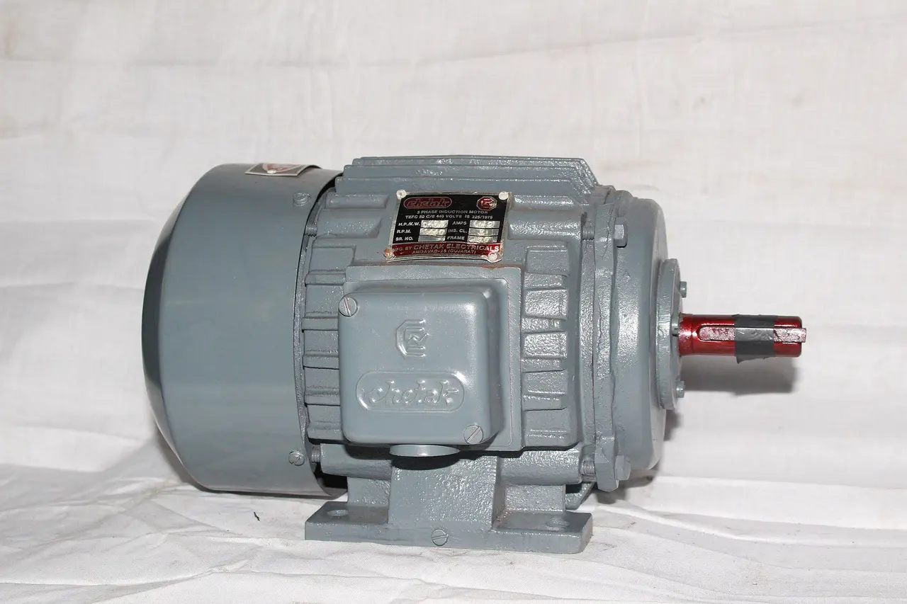
When a three-phase induction motor (Figure 1) is switched straight onto the supply (direct-on-line, DOL), it draws about 6–8 times its rated current for a few seconds. Small motors cope, but from roughly 7.5–11 kW upwards this causes a voltage dip across the whole workshop, nuisance breaker trips, flickering lights and trouble for other machines.
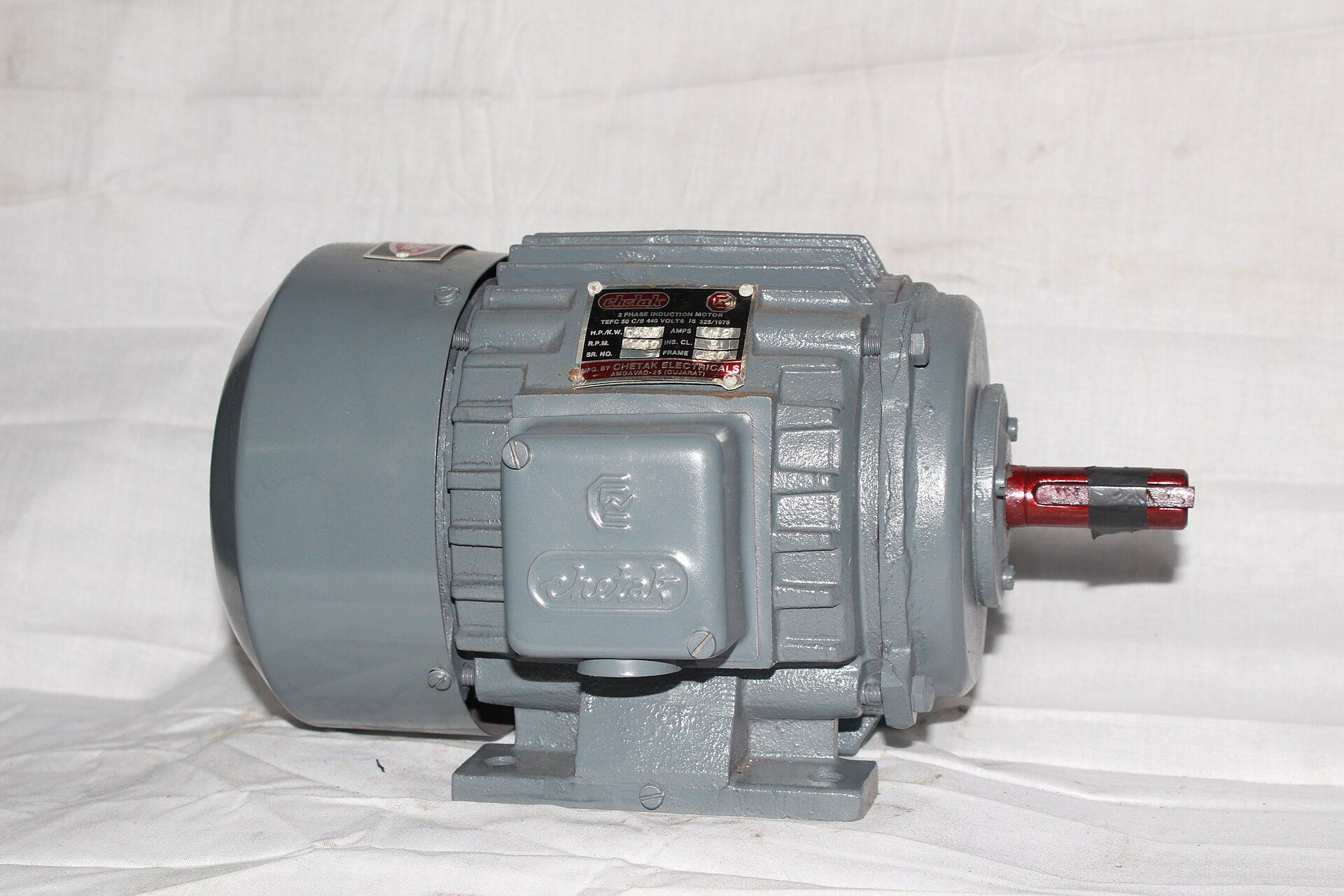
Photo: KishanMalaviyaatCHETAK ELECTRICALS / Wikimedia Commons, CC BY-SA 4.0

How the current is reduced
Every motor has three windings. In star, each winding sees the phase voltage of 220V; in delta, each sees the line voltage of 380V. The winding voltage drops by √3 (about 1.73), so the line current at start falls to about one third of a direct-on-line start in delta. The trade-off is that starting torque also falls to about one third.
When it works and when it does not
It suits loads that start light: centrifugal pumps, fans, compressors that start unloaded, machine tools that spin up empty. It does not suit loads that are heavy from the first second, such as a crusher full of material or a loaded conveyor, because one third of the torque is not enough; those need a soft starter or a variable frequency drive, which is the next step of the roadmap.
Read the nameplate first
A nameplate reading Δ/Y 380/660V (or 400/690V) means the motor runs in delta at 380V, so it can be star-delta started on a 380V supply. A nameplate reading Δ/Y 220/380V means that on a 380V supply the motor must run permanently in star; if you star-delta it, each winding gets 380V after the changeover and burns out. This is the most dangerous beginner mistake. In Vietnam the low-voltage three-phase supply is commonly called 380V, and newer equipment is often labelled 400V.
The terminal box: six ends U1 V1 W1, U2 V2 W2
Open the terminal box cover (Figure 2) and you see six studs: the top row U1, V1, W1 are the starts of the three windings; the bottom row is usually staggered as W2, U2, V2 so the links sit neatly.
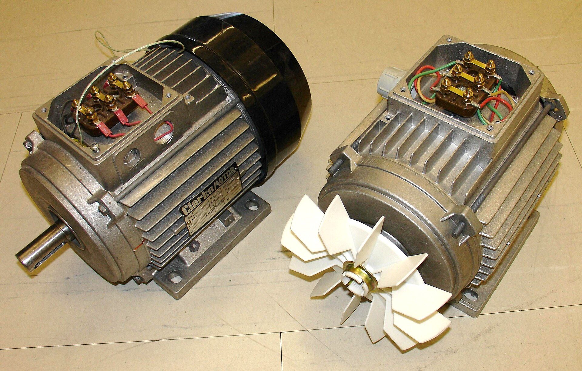
Photo: Zureks / Wikimedia Commons, CC BY-SA 3.0

Star and delta inside the terminal box
| Connection | Links in the terminal box | Supply in | Voltage per winding (380V supply) |
|---|---|---|---|
| Star (Y) | One bar across W2 – U2 – V2 | L1, L2, L3 to U1, V1, W1 | 220V |
| Delta (Δ) | Three vertical links: U1–W2, V1–U2, W1–V2 | L1, L2, L3 to U1, V1, W1 | 380V |
| Star-delta with contactors | Remove all links | Six wires to the panel: U1, V1, W1 and U2, V2, W2 | 220V while starting, 380V while running |
Check the windings before wiring
Remove the links and use a meter to check continuity on each pair U1–U2, V1–V2, W1–W2: three small, nearly equal resistances. Between different windings (for example U1–V1) there must be an open circuit. Test insulation from the windings to the frame with a 500V insulation tester; a common minimum is about 1 MΩ, but check the manufacturer's requirement. If you are not yet confident with a meter, revisit the lesson on using a multimeter as an electrician.
The power circuit
The power circuit carries the heavy current from the breaker to the motor. It has three contactors (Figure 3 shows a three-pole DIN-rail contactor with supply terminals 1/L1, 3/L2, 5/L3 and load terminals 2/T1, 4/T2, 6/T3).
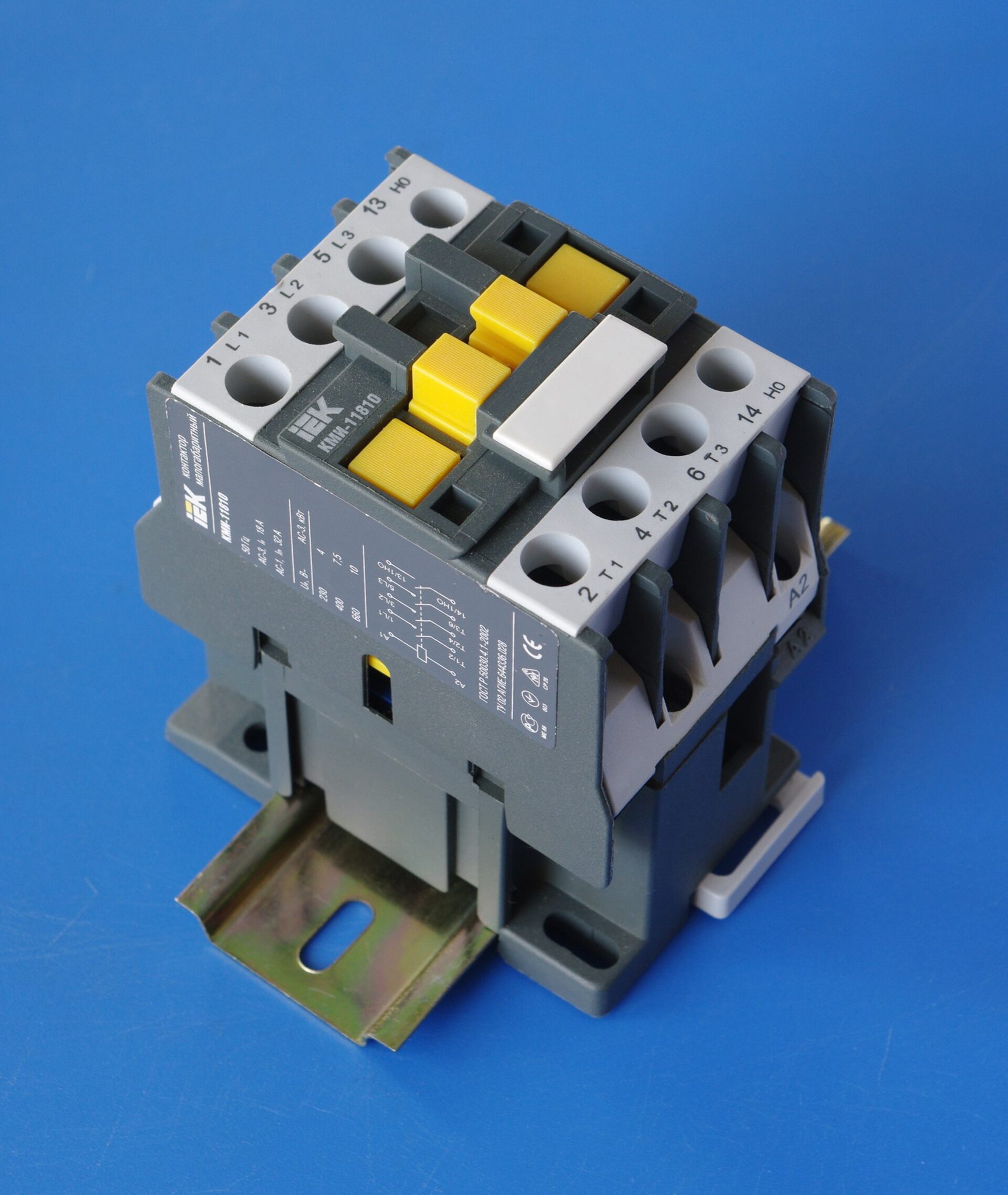
Photo: Kae / Wikimedia Commons, CC BY-SA 3.0

How the current flows
- The supply L1, L2, L3 passes through the main circuit breaker (CB) into the supply side of K1.
- From K1 it passes through the thermal overload relay (OL) to U1, V1, W1 on the motor (cable 1).
- Straight after K1 (before or after the OL, depending on the drawing) a branch feeds K3. The outputs of K3 connect L1 to W2, L2 to U2 and L3 to V2 (cable 2). So when K3 closes, U1 joins W2, V1 joins U2 and W1 joins V2: a correct delta.
- U2, V2 and W2 also connect to the supply side of K2; the three output terminals of K2 are bridged together. When K2 closes, the three winding ends form the star point.
Sizing by current
In delta, the current in each winding equals the line current divided by √3, about 0.58 times the rated current In. So K1 and K3 are sized at about 0.58 In (AC-3 rating) and K2 at about 0.33 In, though many electricians fit K2 the same size as the others for easy spares. An overload relay placed right after K1 (measuring winding current) is set to 0.58 In; one placed before K1 (measuring line current) is set to In.
Phase order and direction
Keep the pairs U1–W2, V1–U2, W1–V2 exactly. Mix them up and at the changeover the motor brakes, jerks hard or causes a short circuit. To reverse the direction, swap two phases at the supply before K1, never inside just one of the two cables.
The control circuit and timer setting
The control circuit runs on 220V (one phase and neutral, or through a control transformer), protected by its own small 2–6A breaker or fuse.
Branches of the circuit
- Supply through the overload relay's normally closed contact 95–96, through the Stop button (normally closed), through the Start button (normally open), with K1's normally open auxiliary contact 13–14 in parallel for self-holding.
- After the self-holding point: K1's coil (A1–A2) and the timer coil KT are energised together.
- Star branch: through the timer's delayed-opening normally closed contact 15–16, through K3's normally closed contact 21–22, to K2's coil.
- Delta branch: through the timer's delayed-closing normally open contact 15–18, through K2's normally closed contact 21–22, to K3's coil.
The two normally closed contacts crossed over in steps 3 and 4 form the interlock: while K2 is in, K3 cannot pull in, and vice versa. Without it, one welded contact is enough for a three-phase short circuit. Terminal numbers can vary by manufacturer; always read the diagram printed on the timer and the panel drawing.
Operating sequence
Press Start: K1, K2 and KT pull in together and the motor runs in star. After the set time the timer changes over: K2 drops out, K2's 21–22 contact recloses, K3 pulls in and the motor runs in delta. Pressing Stop or an overload trip de-energises every coil. Some panels pull in K2 before K1 so the star contactor never switches under load; that is a valid variant, so follow the drawing.
Setting the star-to-delta time
The changeover should happen when the motor reaches about 80–90% of its speed, when the star current has dropped close to steady. Pumps and fans typically need 5–15 seconds. Method: set 10 seconds, clamp a meter around one motor cable, watch the star current fall and then settle; take that time and add 1–2 seconds. Switch too early and the delta current spikes almost as high as a direct start; too late and the motor runs loaded in star for too long, heats up and may trip the overload. Dedicated star-delta timers include a dead time of about 50–100 ms between K2 dropping out and K3 pulling in, so the arc is fully extinguished.
Safety: lock out and tag out before you touch the motor
Working on a star-delta starter means working on a 380V high-current circuit, and someone else may switch it on remotely. LOTO (lockout-tagout) is mandatory, not paperwork. Figure 4 shows a main switch locked with a padlock and tagged "do not switch on".
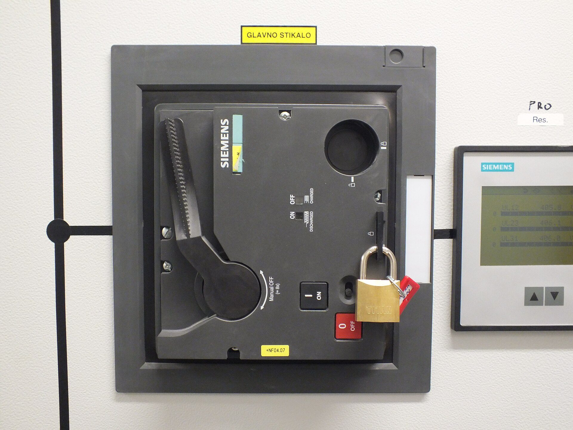
Photo: Svetina D at Slovenian Wikipedia / Wikimedia Commons, Public domain

Safety warning: before opening a terminal box or control panel: (1) tell the operator and stop the machine; (2) switch off the breaker or isolator feeding the panel, lock it with your personal padlock, hang a tag with your name and phone number, and keep the key on you; (3) with a tester or meter you have just checked on a live source, prove there is no voltage between phases and from each phase to earth, at both the breaker input and the terminal box; (4) if the control circuit has a separate supply, isolate and lock that too; (5) beware of a motor being turned by its load (a pump with water flowing back, a fan driven by wind), which can still generate voltage. Do not work on 380V circuits unless you are trained and authorised, never work alone, and never stand on a wet floor. When the job is done, only the person who applied the lock may remove it. For the general principles, see the lesson on 5 mandatory safety rules before you touch any electrical wire.
Test the control circuit off-load
Remove the main fuses or disconnect the power wiring from the motor (or unplug the motor cables at the panel and insulate the ends), and supply only the control circuit. Press Start and watch K1 and K2 pull in, then after the set time K2 drops out and K3 pulls in. Push K3 in by hand while K2 is energised to confirm the interlock works (K3 must not hold). Press the overload relay's test button: everything must drop out.
First run under load
Switch on and bump the motor for a few seconds to check the direction, then run a full star-to-delta cycle with a clamp meter on the cable. The steady current in delta must be below the rated current; if you notice vibration, an unusual growl or a burning smell, stop at once.
Common star-delta wiring mistakes
| Mistake | Symptom | Cause | Fix |
|---|---|---|---|
| Bang and breaker trip at changeover | Loud bang in the panel, blackened contacts | No interlock, timer switching instantly, links left in the terminal box | Wire the crossed interlock, use a star-delta timer, remove all links |
| Motor jerks or brakes at changeover | Speed drops, current spikes very high | U2/V2/W2 connected to the wrong K3 terminals | Rewire as L1–W2, L2–U2, L3–V2 |
| Motor overheats, windings burn within days | Burning smell, low insulation reading | A 220/380V motor star-delta started on a 380V supply | Use only motors rated Δ 380V; a burnt motor must be rewound |
| Overload trips during normal running | Measured current below rating | OL set to In while placed after K1 (should be 0.58 In), or the reverse | Find the OL position on the drawing and set the correct factor |
| Never switches to delta | Stays in star, overload trips | Faulty timer, contacts 15–16 and 15–18 swapped, K2 not dropping out | Test the timer on its own, check K2's auxiliary contacts |
Habits of an experienced electrician
Number the lugs on all six power wires at both ends, photograph the terminal box before removing anything, and write the timer setting and running current inside the panel door. Re-tighten the terminals after the first one or two weeks, because copper expands and contracts with heat.
Worked example: a star-delta panel for a 15 kW pump
An ice factory in Binh Duong is replacing a centrifugal pump. The new motor's nameplate reads 15 kW, Δ/Y 380/660V, In = 29 A, 2,930 rpm. The factory supply is three-phase 380V. The nameplate says Δ 380V, so it qualifies for star-delta starting.
Calculate the currents and size the equipment
A direct-on-line start would draw about 6–7 × 29 = 174–203 A. In star that falls to about one third: 174 ÷ 3 = 58 A up to 203 ÷ 3 ≈ 68 A. Winding current while running: 0.58 × 29 ≈ 16.8 A. Current through K2 in star: 0.33 × 29 ≈ 9.6 A.
| Component | Calculation | Choice | Reference unit price |
|---|---|---|---|
| K1 main contactor | ≥ 0.58 × 29 = 16.8 A (AC-3) | 18 A, 220V coil | 450,000 VND |
| K3 delta contactor | ≥ 16.8 A | 18 A | 450,000 VND |
| K2 star contactor | ≥ 0.33 × 29 = 9.6 A | 12 A | 350,000 VND |
| Overload relay after K1 | Set 0.58 × 29 ≈ 17 A | 12–18 A range | 400,000 VND |
| Star-delta timer | Set from field measurement | 0–30 second range | 350,000 VND |
| Three-phase main breaker | From the manufacturer's coordination table for In = 29 A | 40 A | 900,000 VND |
| Push buttons, pilot lights | Start, Stop, run light, fault light | 1 set | 200,000 VND |
| Total main components | 3,100,000 VND | ||
Check the total: 450,000 + 450,000 + 350,000 + 400,000 + 350,000 + 900,000 + 200,000 = 3,100,000 VND (about 120 USD). That excludes the enclosure, cables, DIN rail, trunking and labour. Prices are 2026 references in Vietnam and vary by brand and region. The motor is fed by two cables, each carrying about 16.8 A; size them from the cable maker's current-rating table and the route length, plus an earth conductor for the motor frame.
Setting the timer on site
The first run uses 10 seconds. The clamp meter shows the star current rising to about 62 A, then falling to about 14 A after 6 seconds and staying there. The electrician resets the timer to 7 seconds (6 + 1). At changeover the delta current briefly jumps to about 45 A, then settles at 24 A, below In = 29 A: a pass. He writes "15 kW – timer 7 s – running 24 A" inside the panel door.
Frequently asked questions
Does a 3 kW motor need a star-delta starter?
Usually not. Small motors can start direct-on-line if the supply is strong enough; star-delta is typically used from about 7.5–11 kW upwards, or when the utility or factory owner requires limited starting current.
Is star-delta better than a VFD or soft starter?
Star-delta is cheap, robust and easy to repair, but it gives a jolt at changeover and low starting torque. A soft starter ramps current up smoothly; a variable frequency drive also controls speed and saves energy on pumps and fans. Choose by load and budget.
Why must the links in the terminal box be removed?
Contactors K2 and K3 do the job of the links. Leave the star link in and closing K3 short-circuits the phases; leave the delta links in and the motor starts direct-on-line, making the star stage pointless.
Can I build this circuit at home to learn?
The control circuit can be practised on a bench with a control supply and lamps standing in for the motor, under an instructor's guidance. The 380V power side belongs in a workshop or vocational school, supervised by a qualified person.
Practice exercises and self-assessment
- Read the nameplates of three motors in a workshop, note the Δ/Y voltages and decide which can be star-delta started on 380V.
- Hand-draw the power and control diagrams with all terminal numbers, the interlock and the overload relay.
- For a motor with In = 22 A, calculate the current to size K1, K2 and K3 and the overload setting when it sits after K1.
- Wire and test the control circuit off-load on a practice bench with the timer set to 8 seconds.
Self-assessment criteria
- Pass: you lock out, tag out and prove dead before opening the panel or terminal box, without skipping a step.
- Pass: the off-load test runs K1+K2 then K1+K3; pushing K3 in by hand while K2 is energised does not hold it; your In = 22 A calculation gives about 12.8 A for K1/K3 and an overload setting of about 12.8 A.
- Not yet: you forget to remove the terminal box links, leave out the interlock, or star-delta a motor rated 220/380V.
Once you can wire a star-delta starter confidently and read motor nameplates fluently, move on to the next step of the roadmap: setting up variable frequency drives and soft starters — smoother starting and speed control for pumps, fans and conveyors.
Keep learning the industrial electrician trade: after starter circuits come VFDs, soft starters, PLCs and control panel building. See the 8-step industrial electrician roadmap to track your progress.