You open the distribution board and one miniature circuit breaker (MCB) feels warm through its front, the plastic around its terminal has turned brown, or it gives a faint buzz when the air conditioner runs. Or the opposite: the toggle will not stay up even though everything on that circuit is unplugged, it flops loosely, or it will not switch off at all. The question is always the same: is the breaker itself faulty, or is it doing its job and telling you about a problem somewhere else?
This guide shows how to tell a worn or damaged breaker from an overload, a loose terminal or a circuit fault, and how to replace an MCB correctly. If your breaker simply trips now and then, start with our article on finding why a circuit breaker keeps tripping (or our RCD tripping guide). Choosing wire and breaker sizes, wiring RCDs/RCBOs and building a new board have their own articles; here we focus only on the breaker that looks, sounds or feels wrong.
Scope of this guide. This article is for trainee and working residential electricians, and for homeowners who want to understand what the electrician is checking, on single-phase 230 V / 50 Hz installations as used in Vietnam. Even with the main switch off, its incoming terminals and the meter side stay live. Homeowners should stick to the cover-on checks below and call a licensed electrician for anything that needs the cover off. Follow current Vietnamese regulations and standards and the manufacturer's instructions for the exact devices in the board. Numbers marked for reference are typical values or examples, not rules.
How an MCB works, and why that matters for diagnosis
A miniature circuit breaker protects the cable of a circuit, not the appliance. Inside the small housing there are two trip mechanisms and a set of contacts:
Thermal trip: a bimetal strip that bends as current heats it and trips the latch on a sustained overload. Because it works by heat, a breaker heated from outside (a hot terminal, a very hot board) can trip below its rating.
Magnetic trip: a coil and plunger that trip almost instantly on a large fault current such as a short circuit.
Contacts and arc chute: the contacts open the circuit; a stack of metal plates breaks up the arc.
Terminals: screw clamps for the supply and the outgoing circuit, where most heat problems start.
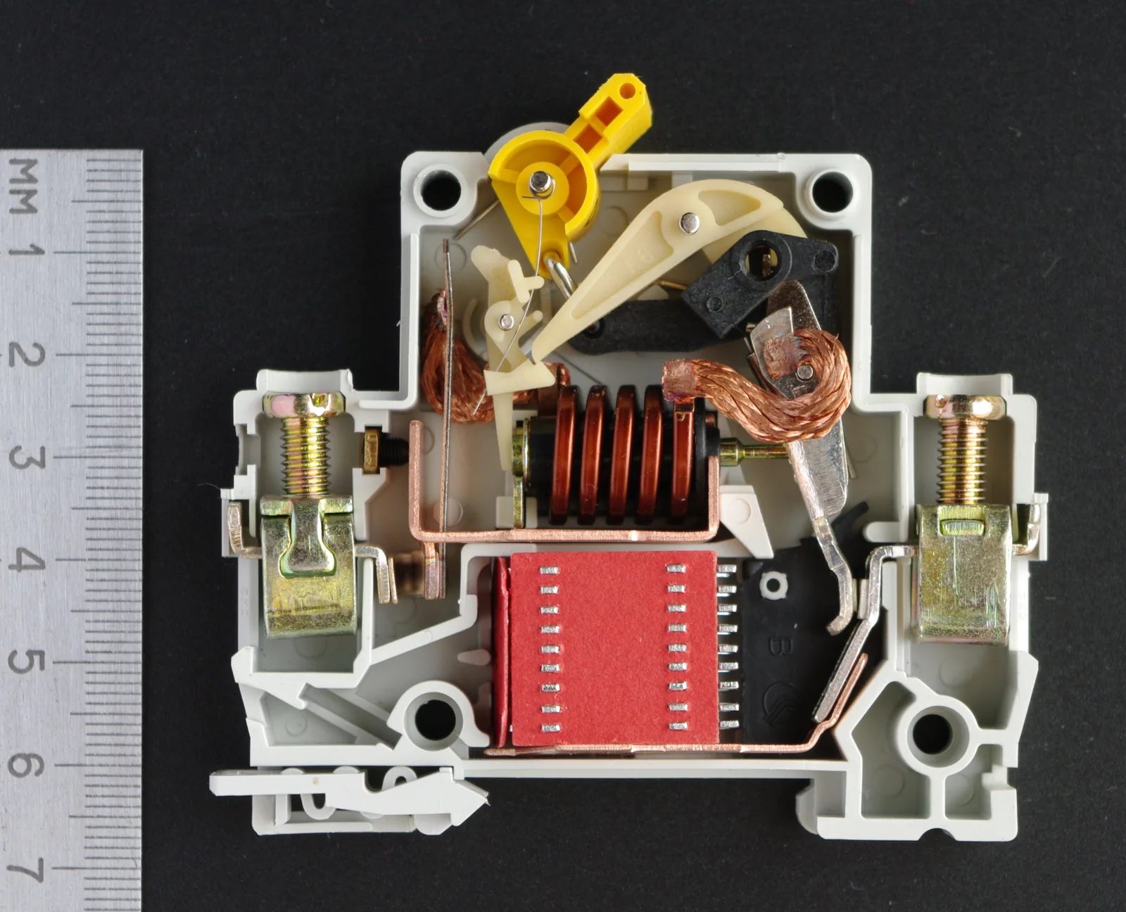
Figure 1. A single-pole MCB with one half of its case removed, next to a ruler in centimetres: the screw terminals are at each end, the copper magnetic-trip coil sits in the middle, the red stack of arc-chute plates is below it, and the toggle and latch mechanism are at the top. (Photo: Kae, Wikimedia Commons, CC BY-SA 3.0)
Two things follow. An MCB is a mechanical device that wears: heavy fault trips erode the contacts and the latch ages. And a breaker gets warm in normal use near its rating. "Warm" is not automatically "faulty"; what matters is how hot, compared with what, and at what current.
Symptoms table: faulty breaker or something else?
In practice, many "bad breaker" calls turn out to be a loose terminal or an overloaded circuit, so check those before condemning the breaker.
Symptom | Most likely causes | Check first | Points to the breaker itself when… |
|---|---|---|---|
Breaker warm or hot to the touch | Loose terminal; circuit near or above rating; hot, crowded board | Clamp-meter current; compare with neighbours; terminals (dead) | Clearly hotter than an identical breaker at similar current, terminals tight |
Buzzing, crackling or hissing | Arcing at a loose terminal or busbar; heavy overload | Locate the device; look for discoloration; measure current | Sound from inside the body at normal current, terminals sound |
Burnt smell, brown or black marks, melted plastic | Overheated terminal: loose screw, damaged conductor | Isolate; inspect terminal, conductor end, busbar | Heat damage on the housing: always replace |
Will not stay ON with all loads on that circuit unplugged or switched off | Short or earth fault in fixed wiring; hard-wired appliance (water heater, air conditioner); faulty breaker | Disconnect the outgoing conductor (dead), try the breaker alone | Still will not latch with nothing connected |
Will not switch OFF, or the circuit stays live with the toggle OFF | Welded contacts, broken mechanism | Proven tester on the outgoing side, toggle OFF | Always: replace immediately |
Toggle loose, mushy, does not click, or sits halfway | Worn latch; or tripped and needs fully OFF before ON | Switch fully OFF, then ON firmly | Still loose or will not latch |
Trips at a current well below its rating | External heating; worn thermal trip; more current than you think | Clamp-meter the real current; terminal temperature | Trips at modest steady current, terminals cool and tight |
Safe first checks you can do without opening the board
These checks are done with the board's front cover (the panel that covers the live parts and leaves only the toggles showing) in place. If the cover is missing, cracked or burnt, do not touch the board; switch off at the main switch only if it is safe to reach it, and call an electrician.
Look, listen and smell
Look for discoloration: brown marks above or below one device, warped plastic, soot near a terminal.
Listen with the house quiet. A healthy MCB is practically silent; buzzing or crackling usually means arcing at a connection.
Smell for hot plastic or a "fishy" smell, typical of overheating insulation.
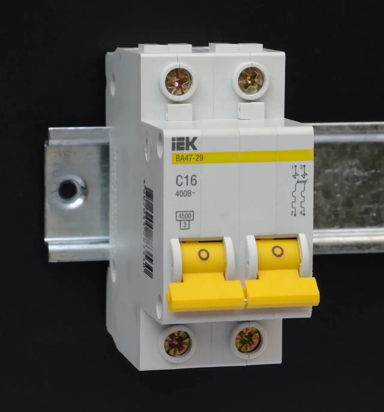
Read the label: rating (e.g. C16), poles, and which circuit it feeds.
Smoke, sparks, melting or fresh soot: stop. Switch off the main switch if it is safe to reach, keep people away and call an electrician.
Thermal check: back of the hand on the cover only
Lightly touch the front plastic face of the suspect breaker with the back of your fingers, then its neighbours. The back of the hand is used so that, if you ever touched something live, the reflex pulls the hand away rather than gripping. Never touch terminals or wires. A breaker you cannot comfortably keep your hand on, or one much hotter than identical neighbours, needs investigation.
An infrared (IR) thermometer gives a number to record, for reference only: shiny metal reads inaccurately, cheap meters measure a spot wider than one breaker, and readings depend on the load at that moment. Use it to compare (this breaker against its neighbour, before against after the repair), not as an absolute limit. Breaker ratings assume a reference ambient temperature given by the maker; check it if the board is somewhere hot, such as under a tin roof.
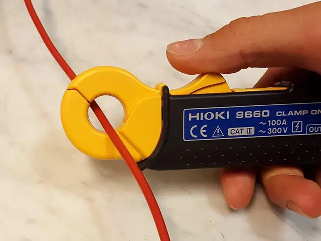
Measure the real load current with a clamp meter
Heat at a "16 A" breaker means little until you know the actual current.
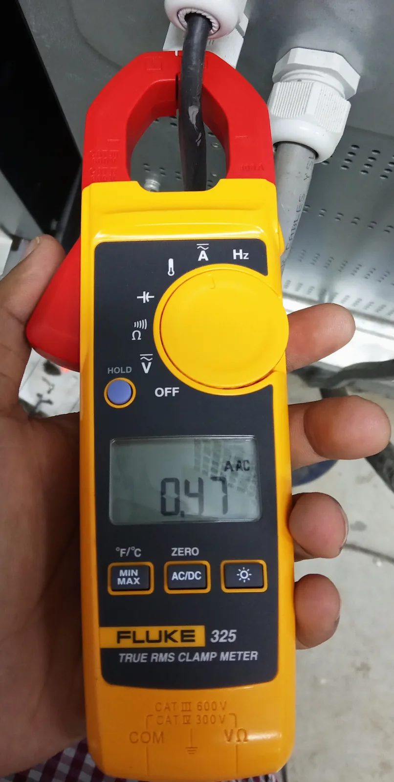
Figure 2. A clamp meter with its jaws closed around a single insulated conductor, showing a reading of 0.47 A AC. Only one conductor goes inside the jaws; line and neutral together cancel and read near zero. (Photo: ZianMan, Wikimedia Commons, CC BY-SA 4.0)
Clamp only the line conductor of that circuit, not the whole cable.
Run the circuit's normal heavy loads together and note the steady current (and the inrush reading, if your meter has one, as compressors start).
Compare with the rating. A circuit near its rating for hours will warm and may trip the breaker; that is an overloaded circuit, not a faulty breaker.
Important: clamping at the board usually means removing the cover with the circuit live. That is work near live parts, for a competent electrician only, with insulated tools, suitable PPE and a meter of suitable category rating; trainees under direct supervision. Where possible, clamp at a safer accessible point, such as a single core in open trunking.
The most common cause of heat: a loose or poor terminal
When a breaker is hot at a current well within its rating, the usual cause is a high-resistance connection: a screw never fully tightened or loosened by years of heating and cooling, a conductor clamped on its insulation, broken strands, or a busbar tooth not seated in the clamp. The resistance makes heat at the terminal, heat oxidises the metal, resistance rises, and the process feeds itself until plastic melts or a fire starts.
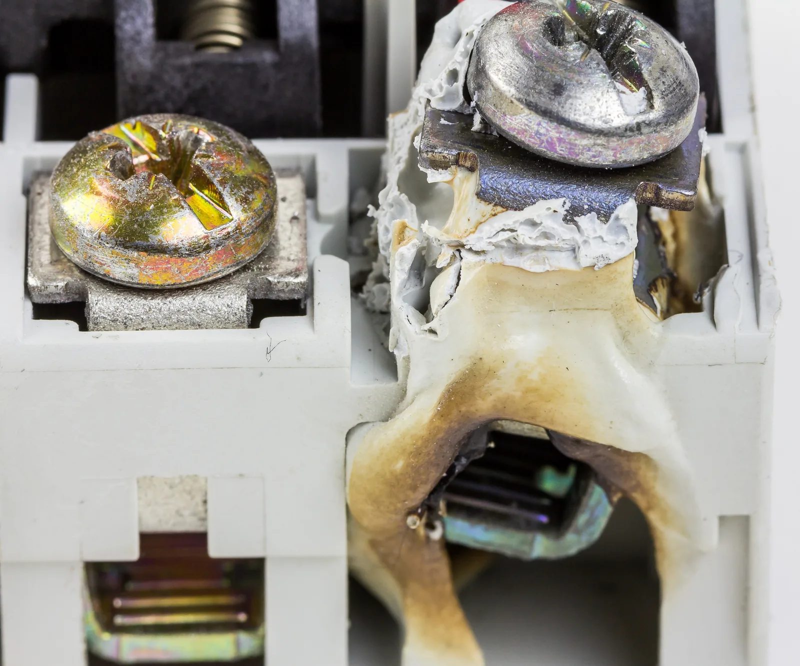
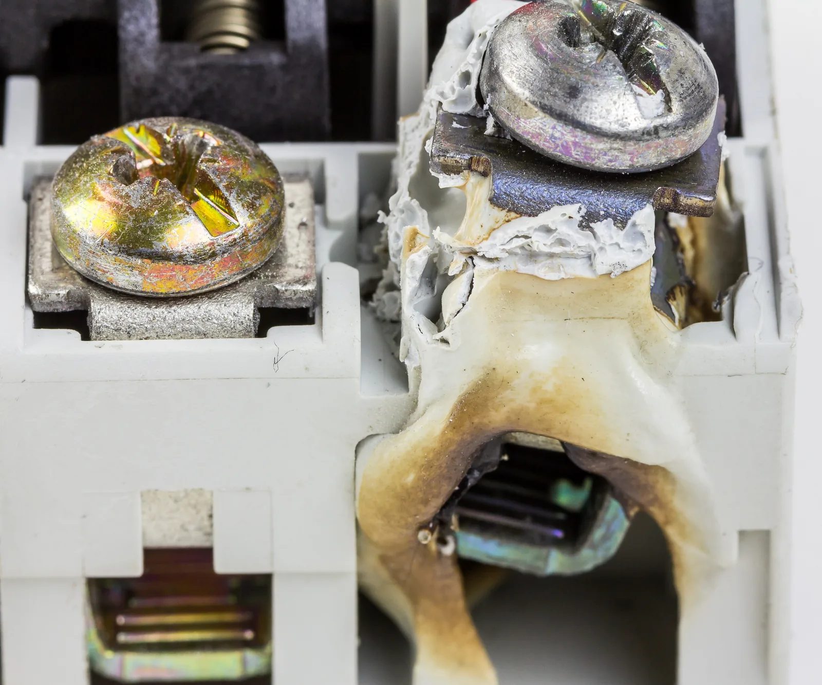
Figure 3. Close-up of the terminals of a failed modular DIN-rail device (a residual current device) with its case removed. The housing around the right-hand terminal has melted, blistered and turned brown from heat, while the identical terminal on the left is undamaged. (Photo: Raimond Spekking, Wikimedia Commons, CC BY-SA 4.0)
Signs that point to the terminal rather than the mechanism:
Heat concentrated at the top or bottom (the terminals), not across the body.
Discoloured insulation or a darkened, stiff conductor end at the terminal.
Aluminium in a terminal not made for it, or aluminium twisted with copper.
Two different-size conductors in one terminal, leaving the smaller loose.
Even if the terminal was the root cause, a breaker whose housing is discoloured, deformed or melted by heat must be replaced: the heat may have affected the thermal trip, plastic and springs. Re-tightening it is not a repair.
Confirming the breaker itself is faulty
These tests are done dead, after isolating as described in the replacement steps below, except where stated.
Test 1: will it latch with nothing connected?
Isolate, prove dead, disconnect the outgoing conductor(s), insulate and secure the ends, restore the supply and switch the breaker ON with nothing connected to its output.
It trips or will not latch: the breaker is faulty. Replace it.
It stays ON: the breaker is probably fine and the fault is in the circuit (a short, damaged cable, a faulty fixed appliance). Do not keep resetting it; find the fault with insulation-resistance and continuity tests (see our tripping-breaker procedure) first.
Test 2: does it really disconnect?
With the breaker OFF and supply on, test its outgoing terminal to neutral and earth with a proven two-pole tester. Any voltage means welded contacts or a broken mechanism: isolate at the main switch, label it "DO NOT USE" and replace it. This is a test on exposed live parts, for a competent electrician only.
Test 3: compare like with like
Compare against an identical breaker at similar measured current. If, with terminals checked (dead) and normal current, it is still clearly hotter, its internal contacts are probably worn. Replace it.
Test 4: feel of the mechanism
A healthy breaker has a definite, positive action. A toggle that is floppy, sticks halfway or must be held up means a worn latch. Replace it; never open or repair an MCB.
Choosing the replacement breaker
The replacement must match the original unless a qualified person has re-checked the circuit design. Never fit a higher-rated breaker to stop heating or tripping: the rating protects the cable. If the old breaker looks wrong for the cable, that is a design question (see our wire and breaker sizing article).
Property | Where to read it | What to match |
|---|---|---|
Rated current (In) | Front label, e.g. "C16" = 16 A | Same rating, unless the circuit design has been re-checked against the cable |
Tripping curve | Letter before the rating: B, C (D is for special motor loads) | Same curve. B trips magnetically at a lower multiple of its rating than C; C is common on household circuits with motors (for reference) |
Number of poles | Width (modules) and markings: 1P, 1P+N, 2P | Same: if the original switched line and neutral, so must the new one |
Breaking capacity | Number in a small box on the front, e.g. 4500 or 6000 (A) | Equal or higher; typical 4.5, 6 or 10 kA (for reference). Check board documents or the maker |
Maker and series | Brand and model code on the device | Same series if busbar-fed, so the comb fits and the profile suits the cover |
Voltage and frequency | Front or side label | Suitable for 230 V / 50 Hz |
Terminal type and conductor range | Side label or datasheet | Takes the existing conductors and busbar type (pin or fork) |
Origin | Packaging, supplier | Reputable supplier; counterfeits may not trip properly |
Practical example. The kitchen breaker in a terraced house is labelled C20, 1P+N, 6000, from one maker's series, and is fed by a busbar comb along the top of the row. The correct replacement is a C20 1P+N with a breaking capacity of at least 6 kA, from the same series, so the busbar pins seat correctly. A cheaper B20 from another maker may not take the comb, and its different curve could trip when a compressor starts.
Replacing the MCB step by step
This is work for a competent electrician or a supervised trainee. Warn the occupants, have the breaker, tools, ferrules and labels ready, and bring a head torch.
Step 1: Isolate at the main switch and prove dead
Switch off the individual breaker, then switch off the main switch of the board. Lock it off if the device allows, and put a warning tag on it.
Remove the board's front cover. The incoming terminals of the main switch, the supply cable and the meter side are still live: keep hands and tools away, and shroud them if exposed.
Prove dead with an approved two-pole voltage tester: first prove the tester on a known live source (a proving unit or a known live point), then test at the breaker you will work on between line and neutral, line and earth, and neutral and earth, on both its incoming and outgoing terminals, then prove the tester again on the known source. A non-contact voltage pen alone is not enough.
Check for other sources (solar inverter, generator, UPS) and isolate them too.
Step 2: Record and disconnect
Photograph the row and label the conductors.
Loosen the outgoing terminal(s) and withdraw the circuit conductor(s).
If fed by individual wires (looped links), remove them, noting where they came from.
If fed by a busbar comb, loosen its terminals on this and usually the neighbouring breakers so the comb can be lifted or slid free. Do not bend the teeth.
Figure 4. A copper busbar comb in a grey insulating cover, used to feed a row of modular breakers. Each fork-shaped tooth goes into the supply terminal of one breaker. Spacing and tooth shape must suit the breakers. (Photo: Dmitry G, Wikimedia Commons, CC BY-SA 3.0)
Step 3: Remove the breaker from the DIN rail
Modular breakers clip onto a 35 mm DIN rail. Lever the spring clip down with a flat screwdriver and tilt the breaker off. A darkened, pitted or melted busbar means the comb must be replaced too, and arcing marks are a reason to assess the whole board.
Inspect the conductor ends. If the copper is blackened, the insulation brittle or strands broken, cut back to clean conductor if length allows; otherwise extend with a proper connector or replace the cable.
Step 4: Fit the new breaker and connect
Clip the new breaker onto the rail, fully latched and level with its neighbours.
Refit the comb or supply wires. The comb tooth must sit inside the clamp, not on top of it or behind the clamp plate.
Strip to the length marked on the breaker: no bare copper outside, no insulation inside the clamp.
On stranded conductors, crimp a bootlace ferrule of the right size with a proper tool. Do not tin ends with solder; it creeps under pressure and the joint loosens.
Tighten to the torque stated by the breaker's maker (on the device or datasheet), ideally with a torque screwdriver. Too loose causes heat; too tight can crack the terminal.
Tug-test each conductor.
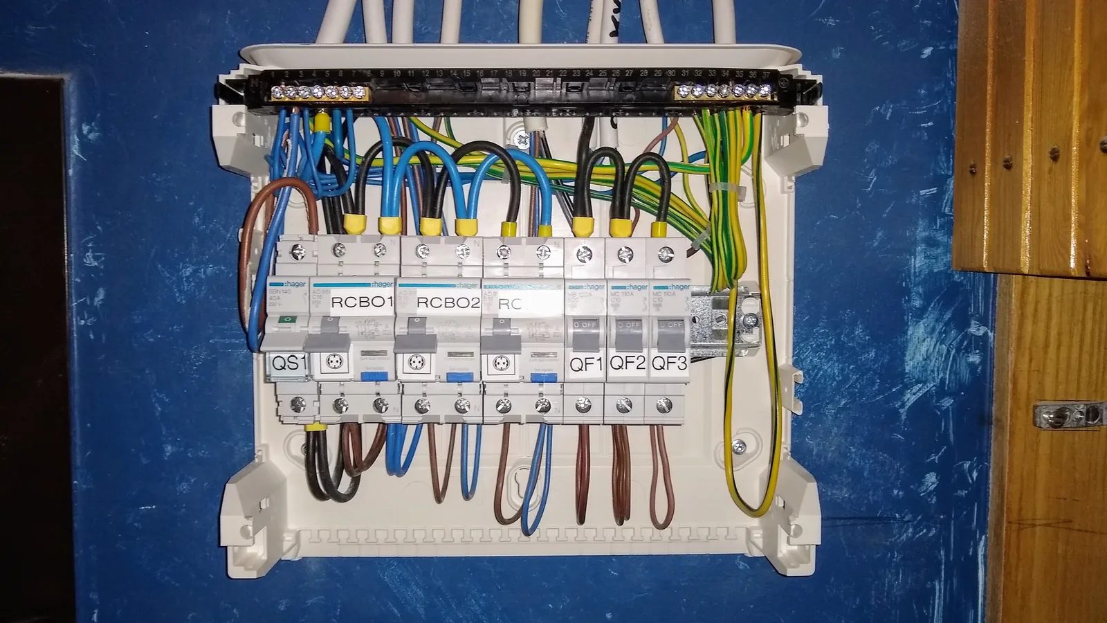
Figure 5. A home distribution board with its front cover removed, showing a main switch labelled QS1, RCBOs and three MCBs labelled QF1–QF3 on a DIN rail. Short links loop the supply between devices, the conductor ends have yellow ferrules, and the terminal bars are along the top. Clear labels make it easy to isolate the right circuit. (Photo: Dmitry G, Wikimedia Commons, CC BY-SA 3.0)
Step 5: Check before restoring power
Every screw tight, no visible copper or stray strands, comb seated, no tools or offcuts left. Then do the dead tests below.
Testing after replacement
Dead tests
Continuity: the circuit's earth conductor is continuous, and line and neutral reach the outlets.
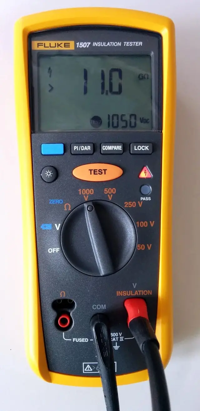
Insulation resistance: with electronics unplugged, test L–N, L–E and N–E with an insulation tester at the voltage specified for 230 V circuits. A low reading means a wiring fault to find before energising (see our insulation-resistance testing article).
Polarity: the breaker is in the line conductor (both L and N for a 2-pole device).
Live tests and load test
Refit the cover, restore the main switch and switch the new breaker ON; it should latch firmly.
Check the circuit works and the voltage is normal.
Run the usual heavy loads and clamp-meter the current at a safe point.
After running under normal load for a while (for reference, half an hour or more), re-check its temperature on the cover against its neighbours. A hot new breaker means a connection problem remains.
Record the fault, current, test results and breaker details; update labels.
If the maker recommends re-checking terminal tightness after a period of service, include it in your handover.
When to call the power company or a licensed electrician
Stop and get the right people involved in these cases:
The main switch is hot, buzzing or discoloured: its incoming side cannot be made dead from inside the house.
Anything on the meter side (meter, seals, service cable): contact the local power company (in Vietnam, your local EVN power company) and never break seals.
Arcing marks on the busbar, soot across several devices, or a melted rail or cover: the whole board needs assessment.
Overheating on several circuits, aluminium wiring or an overcrowded board: a design review by a licensed electrician.
Any time you are not confident you can isolate and prove dead.
Safety checklist
Cover-on checks only (look, listen, smell, back of the hand on the front plastic) unless you are competent and equipped for work inside the board.
Live measurements inside the board only by a competent electrician with insulated tools, PPE and a suitably rated meter.
Isolate at the main switch, lock off and tag; remember the main switch incoming terminals and meter side remain live.
Prove dead with a two-pole tester proven on a known live source before and after testing.
Check for solar, generator or UPS back-feeds.
Replace any breaker with heat damage; inspect and cut back damaged conductor ends.
Match rating, curve, poles, breaking capacity and busbar compatibility; never upsize to stop heat or trips.
Ferrules on stranded conductors; tighten to the maker's torque; tug-test.
Dead tests before energising; load test and temperature re-check after.
Call the power company for the meter side; call a licensed electrician for a hot main switch or busbar arcing.
Frequently Asked Questions
Is it normal for a circuit breaker to feel warm?
Slightly warm near its rating, yes. It should not be too hot to keep your hand on, and should match an identical breaker at similar current. One much hotter than the rest needs checking.
Can I just tighten the screws on a hot breaker?
Only after isolating and proving dead, and only if there is no heat damage; otherwise replace the breaker and cut back the conductor. Never tighten terminals live.
My breaker won't reset even with everything unplugged. Is it broken?
Not necessarily: hard-wired appliances or the wiring itself may be faulty. Disconnect the outgoing conductor (dead) and try it with nothing connected. If it still will not latch, the breaker is faulty.
Why does my breaker buzz?
A healthy MCB is practically silent. Buzzing usually means arcing at a loose connection, heavy overload or a failing breaker. Reduce the load and have it inspected urgently.
Can I replace a breaker with a different brand?
For individually wired breakers, a reputable brand with the same rating, curve and poles and at least the same breaking capacity is usually fine. On a busbar comb, stay with the same series or replace the comb with one that suits every device.
Should I fit a bigger breaker so it stops getting hot?
No. Heat at normal current means a bad connection or worn breaker; trips from overload mean the breaker is protecting the cable. Fix the connection, replace like for like, or split the load onto another designed circuit.
How long does an MCB last?
There is no single figure; it depends on quality, heavy-fault trips, board temperature and connection quality. Replace on the symptoms in this guide or the maker's advice.
Practice Exercises
Diagnose from symptoms. A C16 breaker for a bedroom circuit feels warm at its top end. A clamp meter reads 4 A on the line conductor with the air conditioner running. The neighbouring C16 carries 5 A and feels cool. Give the likely cause and your checks. (Answer: a poor connection at the top terminal, since current is well under rating. Isolate, prove dead, inspect for heat damage, re-make the connection or replace breaker and conductor end, re-check under load.)
Breaker or circuit? A breaker trips instantly every time it is switched on, even with all plugs removed. Describe the test that decides between breaker and wiring, and your action for each result.
Read the label. For three breakers, record rating, curve, poles and breaking capacity, and specify a correct replacement.
Isolation drill. On a training board: switch off, lock and tag, name the parts still live, prove the tester, test all combinations, re-prove. Have your supervisor check each step.
Terminal practice. Crimp ferrules on scrap stranded conductors, fit them into a breaker, tighten to the maker's torque and pull-test.
Client explanation. In three sentences, explain why you are fitting the same 20 A rating, not the 32 A the client asked for.
A hot, buzzing or mushy breaker is a warning, not a nuisance. Measure before you judge, check the terminals before you blame the breaker, replace anything that has been damaged by heat with an exact match, and always prove the work dead and re-check it under load before you leave.