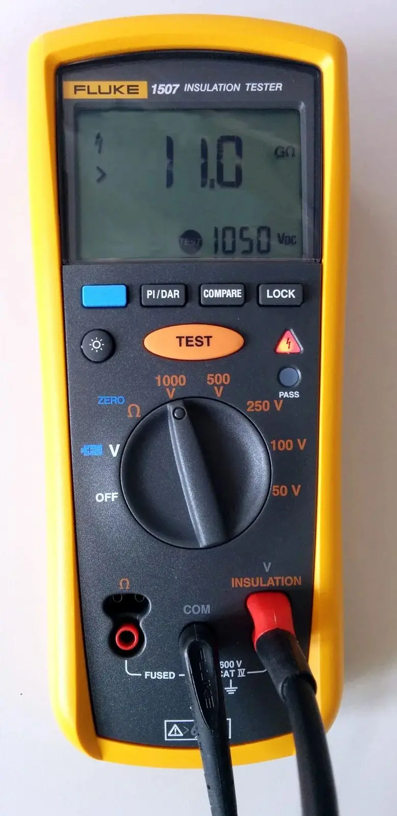
A house has just been rewired and the client wants the power on today. Another client's ground floor was flooded last week. A third has an RCD that trips "for no reason" every time it rains. In each case the question is whether the insulation around the wiring is still doing its job, and a multimeter cannot answer it. The tool for this is an insulation resistance tester, often called a megohmmeter or, on site, a "megger".
This guide explains what the test measures, when to do it, how to prepare a house so the test is safe and meaningful, how to connect the tester, how to read the numbers and how to track down the fault.
Scope of this guide. This article is for trainee and working residential electricians on single-phase 230 V / 50 Hz installations, as used in Vietnam. An insulation resistance test is done on dead, isolated circuits, but the tester itself produces several hundred volts DC, enough to give a painful and dangerous shock. Only a competent person, following current Vietnamese regulations and standards and the tester manufacturer's instructions, should carry it out. Trainees should do it under supervision. Numbers marked for reference come from the international standard IEC 60364-6 or are worked examples; always check the edition and national rules that apply to your job.
What an insulation resistance test measures
Every conductor in a house is wrapped in insulation: the PVC around each core, the outer sheath and the plastic of switches and sockets. Good insulation lets almost no current pass between line (L), neutral (N) and earth (E). Damaged, damp, overheated or aged insulation lets a small current leak through.
The insulation tester applies a DC test voltage (usually 500 V for 230 V house wiring) between two groups of conductors, measures the tiny current that flows, and displays the result as a resistance, normally in megohms (MΩ). One megohm is one million ohms. Healthy insulation reads high, often many tens or hundreds of megohms, or simply shows "greater than" the top of the meter's range. A low reading means current has a path through or around the insulation.
The test voltage matters. A multimeter's resistance range uses only a few volts, so a cable with a nail through it, a hairline crack or a damp junction box may still read "open" (OL) on a multimeter, then break down when 230 V AC with a peak of about 325 V is applied in normal use. Testing at 500 V DC stresses the insulation above its normal working peak and shows up weaknesses before they cause a shock, a fire or a tripping RCD.
Insulation tester, megohmmeter or "megger": the tool
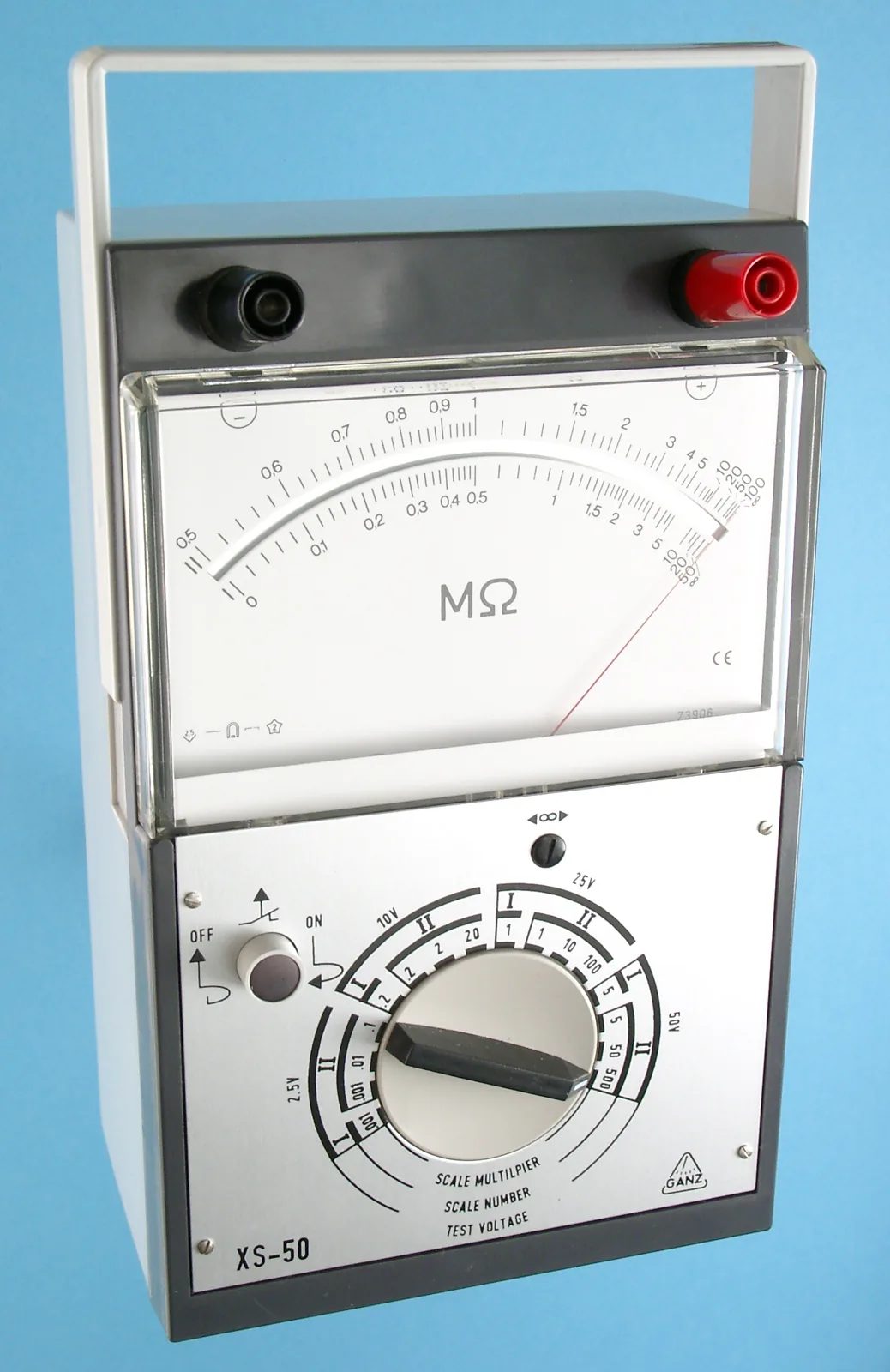
Figure 1. An analogue low-voltage insulation tester: the MΩ scale on the meter face, two test terminals at the top (black and red), and a rotary selector that sets the scale and test voltage. Modern digital testers do the same job with a numeric display. (Photo: Tambo, Wikimedia Commons, CC BY-SA 3.0)
"Megger" is actually a brand name that became the everyday word for the instrument, in the same way some people say "hoover" for a vacuum cleaner. Whatever the name, a tester suitable for residential work should have:
Selectable test voltages, at least 250 V and 500 V DC. Many models also offer 50 V, 100 V and 1000 V.
A range that reaches well above the pass value, for example up to several hundred megohms or more, so you can tell "just passing" from "excellent".
A live-circuit warning that shows or beeps if voltage is present on the leads, and ideally blocks the test.
Automatic discharge of the circuit after the test, with a voltage display that shows the circuit falling back to zero.
A safety category (CAT) rating according to IEC 61010 that suits a distribution board, such as CAT III 600 V or higher, and leads and probes with finger guards.
When to do an insulation resistance test
Before energising new or rewired installations. This is part of the initial verification of any new circuit. It catches cables damaged during installation: a screw through a cable behind a socket box, a sheath crushed by a board cover, a core nicked while stripping.
After adding or altering a circuit, at least on the part you worked on.
After flooding, leaks or water ingress, before switching the supply back on.
When an RCD trips repeatedly and unplugging the appliances does not clear it, which points to the fixed wiring.
During periodic inspections and checks of old houses before buying, renting out or renovating.
Step 1: Plan the test and inform the occupants
Everything in the house will be without power during the test, and some equipment must be unplugged or disconnected. Before you start:
Agree a time with the client and warn them that routers, cameras and fridges will be off for a while.
Ask about equipment that must not lose power, such as medical devices or aquarium pumps, and plan for it.
Get a sketch or a list of the circuits in the board. If the board labels are missing or wrong, note that as a defect for the report.
Prepare a results sheet: circuit name, breaker rating, cable size if known, test voltage, L–N, L–E and N–E (or L+N–E) readings, and remarks.
Step 2: Isolate, lock off and prove dead
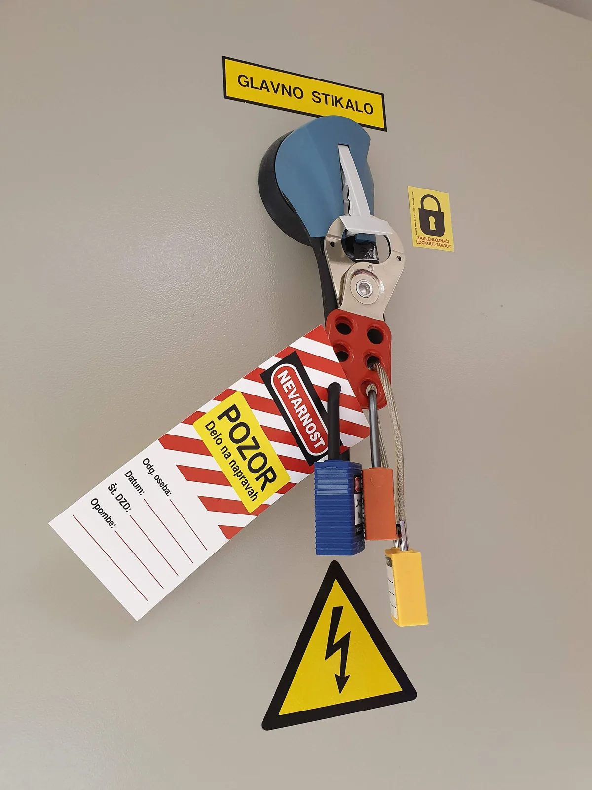
Figure 2. A main switch locked off with a group lockout hasp, several personal padlocks and a danger tag, below a yellow electrical hazard sign. The labels are Slovenian: "NEVARNOST" means danger and "POZOR – Delo na napravah" means caution, work on equipment. At home you can use a breaker lock and a written tag in the same way. (Photo: Jurij Žvab, Wikimedia Commons, CC BY-SA 4.0)
Switch off the main switch of the installation. It should be a double-pole device that disconnects both line and neutral. If the main device switches the line only, read the section on neutral below before testing to earth.
Lock it off and tag it so nobody can switch it back on while you are working. A breaker lock and padlock are better than tape and a note; keep the key in your pocket.
Prove dead with an approved two-pole voltage tester: check the tester on a known live source, test between L–N, L–E and N–E at the outgoing side of the main switch and on each circuit you will test, then check the tester again on the known source. A non-contact voltage pen alone is not enough to prove a circuit dead.
Check for other sources: a generator, a solar inverter with battery, a UPS or a second supply. Each must be isolated too.
Step 3: Disconnect loads and sensitive equipment
This step decides whether your readings mean anything, and whether you damage the client's equipment.
Unplug every appliance from every socket on the circuits under test: TVs, chargers, computers, washing machines, fridges, extension leads with surge protection.
Switch off or disconnect fixed appliances at their own double-pole switch or isolator: water heaters, air conditioners, pumps, cookers.
Lighting: anything connected between L and N (lamps, LED drivers, fans) makes an L–N test read near zero because you are measuring through the load. Either remove the lamps or disconnect the fittings for the L–N test, or skip L–N on lighting and test only L+N to earth (see Step 5).
Electronic devices that can be damaged by 500 V DC must be disconnected: dimmers, smart and Wi-Fi switches, PIR motion sensors, electronic timers, doorbell transformers, mains-powered smoke alarms, LED drivers and some RCDs or RCBOs with electronic circuits. Check the manufacturer's instructions.
Surge protective devices (SPDs) are designed to conduct when voltage rises, so they will distort the reading and may be stressed. Disconnect them during the test, or if that is not practical, IEC 60364-6 allows the test voltage for that part to be reduced to 250 V DC (for reference; the minimum required value stays the same).
Lighting switches ON (after removing the lamps), so the switched line conductors to the fittings are included in the test. Two-way switch circuits should be tested with the switches in each position, so both strappers are included.
Write down everything you disconnect. At the end of the job, everything goes back, and you check it works.
Step 4: Check the tester before use
Inspect the leads and probes: no cracks, no exposed metal, finger guards intact.
Check the battery level. A weak battery may not hold the full test voltage on long circuits.
Select the insulation function at 500 V. With the leads apart (open circuit), press TEST: the display should show the maximum or "greater than" value.
Touch the probes together and press TEST briefly: the display should show close to 0 MΩ. This proves the leads and the tester are working.
Step 5: Connect and carry out the tests
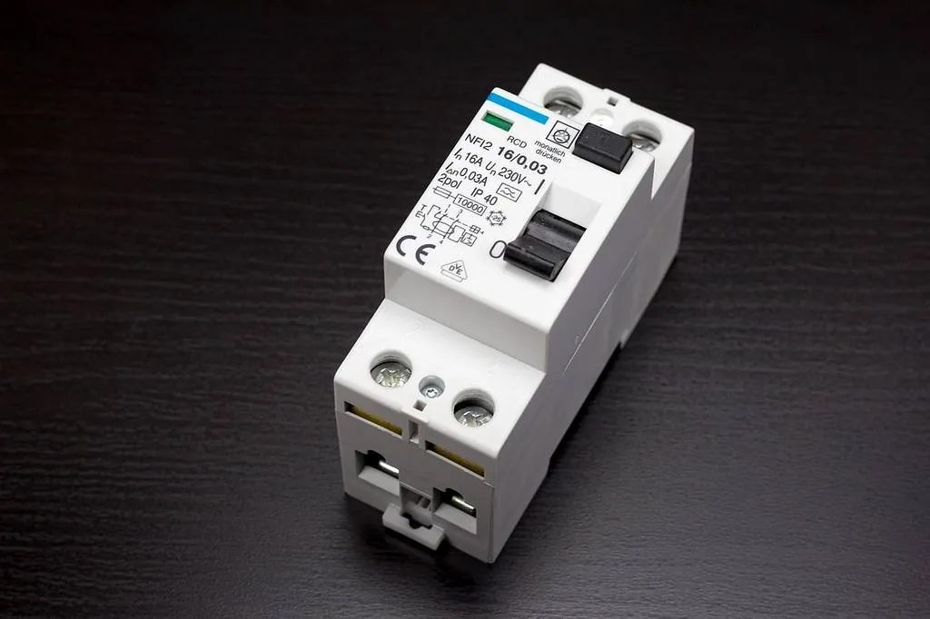
Figure 3. A two-pole residual current device (RCD) rated 16 A, 0.03 A (30 mA), 230 V, with its test button and terminals for line and neutral. Some RCDs and RCBOs contain electronics, so check the manufacturer's instructions before applying a 500 V test across them. (Photo: Diermaier, Wikimedia Commons, CC0)
There are three pairs of conductors to check on a single-phase circuit:
Line to earth (L–E): the most important for shock protection and RCD trips.
Neutral to earth (N–E): a neutral leaking to earth is a classic cause of RCD trips that only happen when a particular load is switched on, or of RCDs that trip with no load at all.
Line to neutral (L–N): shows damage between the two current-carrying conductors. Only meaningful when all loads are disconnected.
Option A: Whole installation from the board
With the main switch off and locked, switch all circuit breakers ON, so all final circuits are connected to the outgoing side of the main switch.
At the outgoing terminals of the main switch, link line and neutral together with a short test lead, then test between this L+N link and the main earth terminal. Linking L and N together protects any equipment you missed in Step 3, because there is no voltage between L and N during the test.
Press and hold TEST until the reading settles. On long or many circuits it may climb for a few seconds as the cable capacitance charges. Record the steady value.
If all loads are disconnected, remove the link and test L–N as well.
Let the circuit discharge. Release the TEST button with the probes still connected and wait until the tester shows the voltage has dropped to zero, or follow its discharge indication. A long cable can hold a charge that will give you a shock.
Option B: One circuit at a time
If the whole-installation reading is low, or you are testing a single new circuit, test each circuit separately. Switch that circuit's breaker off, disconnect its line and neutral conductors from the breaker or RCBO and from the neutral bar (so you are testing the cable and accessories only), and repeat the L+N–E and L–N tests at the conductor ends. Reconnect firmly and tighten to the correct torque when you are finished.
Why the neutral must be separated from earth
In most supplies the neutral is connected to earth somewhere: at the distribution transformer, and in TN-C-S systems also at the origin of the installation. If the house neutral is still connected to that point during your test, an N–E or L+N–E test will read near zero even though the wiring is perfect, because you are measuring through the intentional neutral–earth connection. Opening a double-pole main switch separates the installation neutral from the supply. If the main device is single-pole, you must disconnect the incoming neutral (or the circuit neutrals from the neutral bar) before testing to earth. In TN-C-S systems never remove the main neutral–earth link at the origin yourself unless you are authorised and the supply is isolated by the utility; test circuits individually instead.
Step 6: Read and interpret the results
IEC 60364-6, the international standard on verification of low-voltage installations, gives the following minimum values (for reference; confirm the edition and any Vietnamese standard that applies to your project):
Circuit nominal voltage | DC test voltage | Minimum insulation resistance (for reference) |
|---|---|---|
SELV and PELV (extra-low voltage) | 250 V | 0.5 MΩ |
Up to and including 500 V (includes 230 V house circuits) | 500 V | 1.0 MΩ |
Above 500 V | 1000 V | 1.0 MΩ |
The minimum is a pass/fail line, not a sign of healthy wiring. In practice:
New wiring in good condition usually reads far above the minimum, often at or beyond the top of the meter's range. A brand-new circuit that reads only a few megohms deserves a closer look even if it technically passes. Some national guidance, for example the UK guidance on BS 7671, asks for further investigation when an individual circuit reads below 2 MΩ (for reference).
Compare circuits with each other. If five similar socket circuits read over 200 MΩ and the sixth reads 3 MΩ, the sixth has a problem.
Parallel circuits lower the reading. Insulation resistances of circuits tested together combine like resistors in parallel. For example, ten circuits each at 50 MΩ tested together read about 5 MΩ. That is why a whole-installation reading is always lower than the individual circuits, and why a low whole-installation figure should be followed by circuit-by-circuit tests before you conclude anything.
Conditions and trends matter. Humid weather or a house closed for months can lower readings, so record the conditions. If a circuit read 200 MΩ last year and 10 MΩ today, something has changed, even though 10 MΩ still passes.
Step 7: Find the faulty circuit and the exact fault
Once you know which test is low (L–E, N–E or L–N), you narrow it down by splitting the circuit, the same way you would search for any fault:
Split by circuit. Test each circuit separately (Option B) to find the one with the low reading.
Check what is still connected. Many "faults" turn out to be a forgotten appliance, an outdoor light or an SPD still in circuit.
Split the circuit. On a socket circuit, open a socket in the middle of the run and disconnect the outgoing cable. Test each half. Keep halving until you find the section with the low reading.
Inspect the likely spots in that section: socket and switch boxes where screws may have pierced cables, places where a nail or drill has gone through a wall, outdoor boxes and lights where water collects, bathroom fittings, cables crushed under board covers or floor boards, and old rubber or cloth-insulated cable that has become brittle.
Test fixed appliances separately. Water heater elements are a common source of low L–E readings. With the appliance isolated and disconnected, test between its joined L–N terminals and its earth terminal or metal case, following the manufacturer's instructions.
Repair, then retest. Replace damaged cable sections or accessories, dry out and reseal outdoor boxes with suitable IP-rated enclosures, and retest the repaired circuit before re-energising.
Drying out wet wiring can raise a low reading, but water that has soaked into cables, sockets and boards can leave contamination and corrosion. After flooding, accessories, boards and devices that were under water are usually replaced rather than reused; ask a licensed electrician to decide.
Reference table: typical situations and what they mean
Situation | What you might see (for reference) | What it usually means / next step |
|---|---|---|
New circuit, all loads disconnected, 500 V, L+N–E | At or beyond the top of the meter's range | Insulation in good condition; record and continue |
Whole installation tested together | Lower than each individual circuit | Normal: insulation resistances are in parallel |
N–E or L+N–E reads close to 0 MΩ on every circuit | Near zero, even on new wiring | Neutral still connected to the supply neutral or the N–E link; separate the neutral and retest |
L–N reads close to 0 MΩ, L–E is high | Near zero between L and N only | A lamp, appliance or driver is still connected; or a real L–N fault. Disconnect loads and retest |
One circuit much lower than similar circuits | A few MΩ when others read hundreds | Damage, damp or a connected device on that circuit; split and investigate |
Below the minimum value | Under 1.0 MΩ at 500 V | Fails; do not energise that circuit until repaired and retested |
Tester shows a voltage warning and will not test | Voltage symbol or beep | The circuit is not dead or has another source; stop and re-isolate |
Common mistakes and how to avoid them
Testing with loads still connected. Gives false low L–N readings and can damage electronics. Unplug, disconnect and write down what you disconnected.
Forgetting the neutral–earth connection. Produces near-zero N–E readings on perfect wiring. Make sure the installation neutral is separated from the supply neutral.
Choosing the wrong test voltage. 1000 V on a house installation with electronics still connected can destroy them; 250 V on a normal 230 V circuit may not reveal weaknesses. Use 500 V for 230 V circuits unless a reduced voltage is justified (for example with SPDs that cannot be disconnected).
Touching the conductors during or right after the test. The test voltage is several hundred volts, and long cables store charge. Keep hands off and let the tester discharge the circuit.
Explaining the results to the client
Clients do not need megohms; they need to know whether their wiring is safe and what to do next. Translate your readings into plain language:
"All the circuits tested well, far above the minimum. The wiring insulation is in good condition, and I have written today's figures in the report so we can compare next time."
"The outdoor lighting circuit is much lower than the rest. Water is getting into the light by the gate. Replacing it with a properly sealed outdoor fitting should stop the RCD tripping when it rains."
Give the client a written record of the date, test voltage, readings per circuit and any defects. It shows you measured instead of guessed.
Safety checklist
☐ Occupants informed; sensitive equipment identified and protected.
☐ Main switch off, locked off and tagged; other sources (generator, solar, UPS) isolated.
☐ Circuits proved dead with an approved two-pole voltage tester, checked on a known live source before and after.
☐ All appliances unplugged; fixed appliances isolated; lamps removed or fittings disconnected for L–N tests.
☐ Dimmers, smart switches, sensors, timers, LED drivers, smoke alarms and SPDs disconnected (or reduced test voltage used where justified).
☐ Installation neutral separated from the supply neutral and any N–E link before testing to earth.
☐ Tester and leads inspected; tester checked open and short before use; CAT rating suitable.
☐ Correct test voltage selected (500 V DC for 230 V circuits, for reference).
☐ Hands off conductors during the test; circuit discharged after each test.
☐ All conductors reconnected and tightened; disconnected devices restored; circuits re-energised and checked; results recorded.
☐ Any circuit that fails is left off, locked and labelled until it is repaired and retested.
Frequently Asked Questions
Can I do an insulation resistance test with a multimeter?
No. A multimeter's resistance range uses a very low voltage, so insulation that is damaged but not completely broken down may still read open circuit. An insulation tester applies 500 V DC or more, which shows up weaknesses that would appear at mains voltage.
What test voltage should I use for 230 V house wiring?
500 V DC is the normal test voltage for circuits up to 500 V, which includes 230 V single-phase house circuits (for reference, IEC 60364-6). A reduced voltage of 250 V DC may be used where SPDs or other equipment cannot be disconnected, and 250 V is also used for SELV/PELV extra-low-voltage circuits.
Will an insulation test damage LED lights or electronics?
It can, which is why loads and electronic devices are disconnected first. Linking line and neutral together for the test to earth gives extra protection, because there is then no voltage across anything connected between L and N. Always check the manufacturer's instructions for devices that cannot be removed.
My RCD keeps tripping, but the insulation test passes. What now?
The fault may be in an appliance rather than the fixed wiring, may only appear when a load is running or wet, or may be a neutral shared between circuits on different RCDs. Test appliances separately, use a leakage clamp with the circuit running, and check for borrowed neutrals. See our guide on why an RCD keeps tripping for a step-by-step procedure.
Why are old insulation testers hand-cranked?
Before compact battery electronics, testers contained a small generator turned by a crank to produce the high test voltage. The operator turned the handle at a steady speed while reading the needle. They still work if they are in good condition and calibrated, but modern battery testers are easier and safer to use.
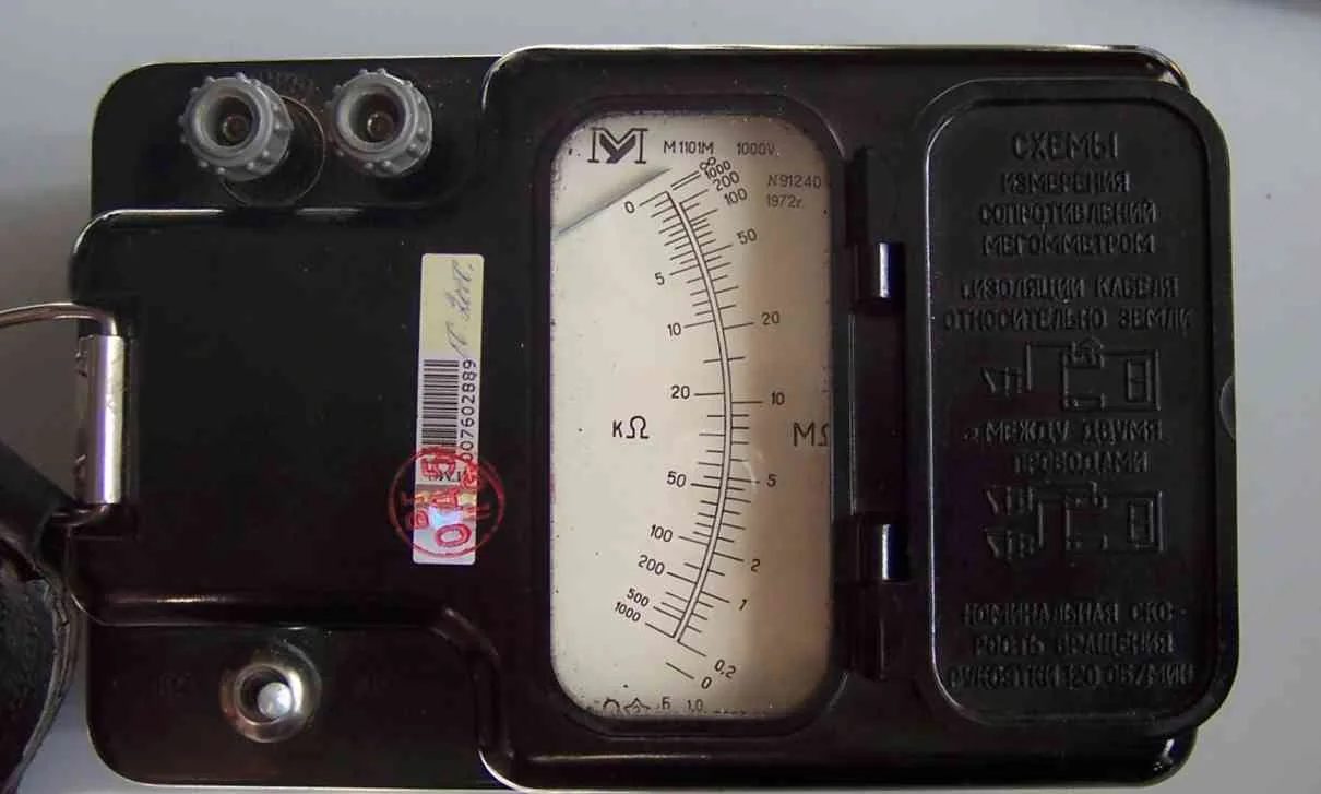
Figure 4. A vintage hand-cranked megohmmeter rated 1000 V, with two test terminals at the top left, a needle scale marked in kΩ and MΩ, and connection diagrams printed on the lid for testing cable insulation to earth and between two conductors. (Photo: Сергин Владимир Александрович, Wikimedia Commons, public domain)
Practice Exercises
Test the tester. Set your tester to 500 V. Record the reading with the leads open and with the probes touching. Explain what each result proves.
Parallel calculation. Four circuits read 400 MΩ, 200 MΩ, 100 MΩ and 50 MΩ separately. Calculate the reading you would expect if all four were tested together. (Answer: about 26.7 MΩ, from 1/R = 1/400 + 1/200 + 1/100 + 1/50.)
Load effect. On a training board, wire a lighting circuit with a lamp. Test L–N with the lamp connected and with it removed. Explain the difference, then test L+N–E with the lamp connected and compare.
Fault finding. Your trainer introduces a fault (for example a damp junction box or a high-value resistor between line and earth) somewhere on a socket circuit. Use the halving method to locate it, and write down each reading you took.
Client report. Using the results sheet from Step 1, write a short report for a client whose outdoor lighting circuit read 0.8 MΩ while all other circuits read over 200 MΩ. Explain the result and your recommendation in plain language.
An insulation resistance test takes preparation, but it is the only way to see inside the walls without opening them. Isolate and prove dead, disconnect what must be disconnected, test at the right voltage, compare circuits with each other, and you will catch damaged wiring before it shocks someone, starts a fire or keeps tripping the RCD.