A multimeter is an electrician's "eyes": it tells you which wire is live, which circuit is broken and which appliance has a fault to its metal case. But using the wrong setting can destroy the meter, or even cause a short-circuit flash right in your hand. In the previous step you learned the switch off – lock out – test again procedure; this lesson teaches you to do the "test" part accurately.
By the end of this lesson, you will be able to:
- Choose the right function, probe socket and CAT safety rating before every measurement.
- Measure the voltage of a 220V/50Hz socket outlet and tell whether it is normal, has a voltage drop or has lost its neutral.
- Check continuity and measure resistance to find broken wires, failed heating elements and appliances with a fault to the case.
- Identify the live (phase), neutral and earth wires, and use a voltage tester pen and a clamp meter within their limits.
At the end there is a worked fault-finding case and practice exercises with self-assessment criteria.
Getting to know the meter
Most digital multimeters have the same main parts:
- Rotary function dial: V~ (AC voltage), V⎓ (DC voltage), Ω (resistance), the speaker symbol (continuity), A (current).
- Probe sockets: COM (black probe), VΩ (red probe for voltage and resistance), A or mA (only when measuring current).
- Safety rating printed on the body, for example CAT II or CAT III. For household wiring, choose a meter rated at least CAT III 600V.
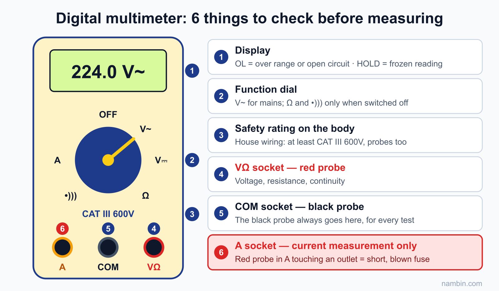
Warning: Never measure voltage while the red probe is plugged into the A socket. In this mode the meter is almost a piece of wire shorting the circuit — touching a socket outlet will cause a short, blow the meter's fuse or throw an arc at your hand.
What does the CAT rating mean?
The CAT rating tells you at which point in the electrical system the meter can withstand overvoltage transients. The grid always carries very short but very high voltage spikes, caused by lightning travelling along the lines or by switching motors and air-conditioner compressors. The closer you are to the source (meter, main board), the more energy those spikes carry. A low-rated meter may handle a normal 220V but flash over inside when a spike arrives, exploding in your hand.
| Category | Typical measuring location | Advice for household electricians |
|---|---|---|
| CAT II | Socket outlets, plug-in appliances | Only enough for outlets and household appliances |
| CAT III | Indoor distribution board, circuit breakers, branch wiring, fixed outlets | The minimum you should use (600V or higher) |
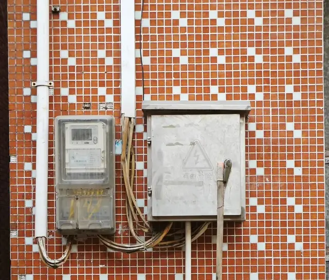
| CAT IV | Origin of supply: utility meter, service cable into the house | This work belongs to the power company; trainees do not do it |
Look at the marking printed next to the probe sockets, and on the probes themselves. The real safety rating of the set is the lower of the meter and the probes. A CAT III meter used with cheap probes that carry no rating is no longer CAT III.
Auto-ranging and manual-ranging meters
An auto-ranging meter only needs to be turned to V~ and it finds the right range by itself — convenient and less confusing for beginners. A manual-ranging meter has several steps such as 200V and 600V; you must pick a step higher than the value you expect. If you pick a lower step, the display usually shows "1" or "OL" (over limit). When measuring mains voltage, always start at the highest step and work down.
Choose a meter with True RMS if you often measure circuits with inverters (variable-speed drives), LED lighting or chargers. Current and voltage in these circuits are no longer a clean sine wave, and an ordinary meter can read noticeably wrong.
Reading the symbols on the display
- OL, or "1" on the left: over range — for resistance this means very high or an open circuit.
- Battery symbol: the battery is low and readings are becoming unreliable.
- Minus sign before the number (V⎓): the red probe is on the negative side — swap the probes.
- HOLD: the display is frozen on an old reading. Many people forget to turn HOLD off and keep reading the same number while the circuit has changed — very dangerous when you are checking "is it dead yet?".
Measurement 1: Measuring socket outlet voltage
- Plug the black probe into COM and the red probe into VΩ. Turn the dial to V~ and, if the meter is not auto-ranging, choose a range above 220V (for example 600V).
- Hold the probes by the insulated part, fingers behind the finger guard.
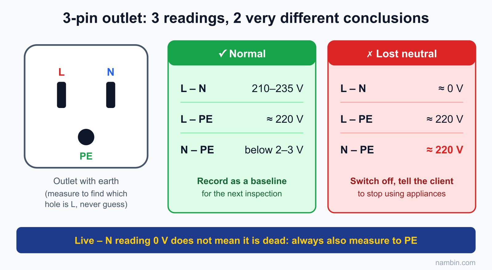
- Insert the two probes into the two holes of the outlet. A normal reading is about 210–235V.
- Also measure between each hole and the earth pin (if the outlet has one): live – earth about 220V, neutral – earth close to 0V.
If both holes read about 220V to earth, the house has very likely lost its neutral — a dangerous fault that must be dealt with straight away.
What counts as a normal voltage reading
Low-voltage mains in Vietnam is 220V, 50Hz. The actual voltage varies with the time of day and the distance to the transformer: a house near the substation at noon may read 230–235V, while a house at the end of the line at the evening peak may be down to about 200V. A few volts of difference is normal. What deserves attention is a large difference between points in the same house.
| Reading | Usual meaning | What to do |
|---|---|---|
| Live – N about 210–235V, N – PE below 2–3V | Normal | Record it as a baseline |
| Live – N 10V or more lower than at the board, under load | Voltage drop from undersized or long wire, or a loose joint | Check joints, review the wire cross-section |
| N – PE several tens of volts | Loose/broken neutral, or poor earthing | Switch off, narrow down the neutral joints |
| Both holes ≈ 220V to PE, live – N ≈ 0V | Neutral lost upstream | Switch off, tell the client not to use appliances |
| Reading fluctuates, keeps jumping | Intermittent joint or poor probe contact | Re-seat the probes, check upstream joints |
"Ghost" voltage on a wire that is switched off
A digital meter has a very high input impedance, so when you measure a wire that is switched off but runs in the same conduit as a live wire, you may see tens of volts, sometimes over 100V. This is induced voltage with almost no energy behind it — but you must not decide on your own that it is a "ghost". The correct approach: switch off the other circuits sharing the conduit as well, or use a meter with a low-impedance mode (usually marked LoZ) to tell the difference. If you are still not sure, treat the wire as live.
Measurement 2: Checking continuity
This tells you whether a wire, fuse or switch is broken. Only measure when the circuit is completely switched off.
- Turn the dial to the speaker symbol (continuity).
- Touch the two probes together: if the meter beeps, it is working.
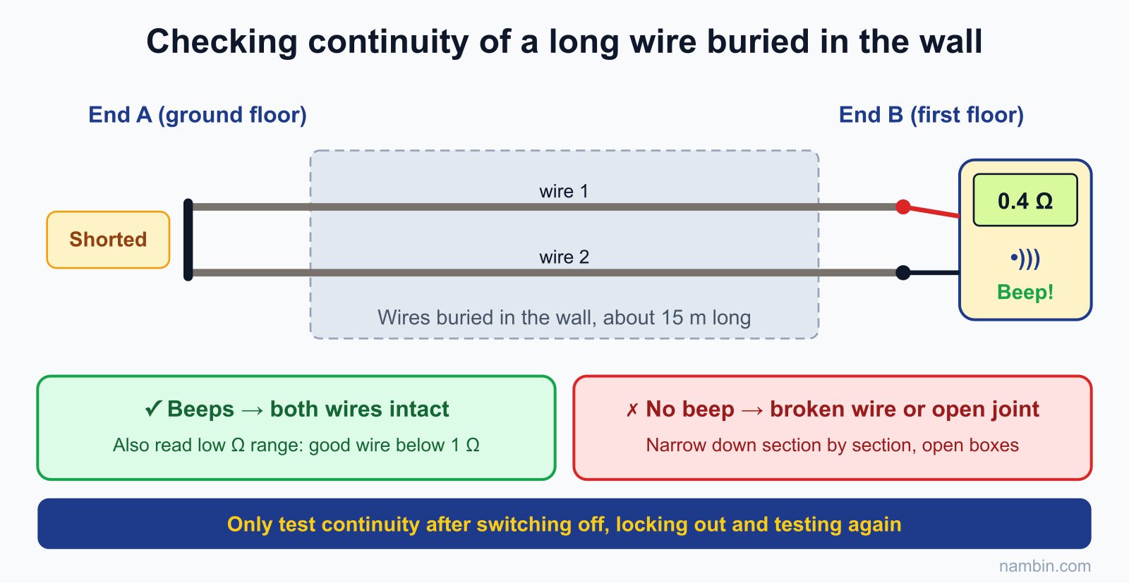
- Place the two probes on the two ends of the wire you are checking. Beep: the wire is continuous. No beep: the wire is broken or a joint is loose.
Tip for long wires buried in walls: twist two wires together at one end, then measure continuity across the same two wires at the other end. The meter now measures the whole out-and-back loop, which is twice the length of the run.
Example: finding the wires of a two-way staircase switch
Narrow Vietnamese tube houses often have a staircase light switched from two floors. Between the two two-way switches run two "strapper" wires. If you replace the switches without marking the wires, you need to identify them again: switch off, remove both switches, on the lower floor short each pair of wires in turn, then go upstairs and check continuity to find which pair are the strappers. Mark them with coloured tape as soon as you find them. The same method works for identifying wires in a conduit full of wires of the same colour.
A beep does not mean the wire is good
The meter usually beeps when resistance is below a few tens of ohms. An oxidised joint can still beep, yet heat up when 10–15A flows through it. So for wires feeding large loads, switch to the lowest Ω range and read the value: good copper wire a few tens of metres long is usually below 1 ohm (after subtracting the resistance of the probes themselves, measured by touching the two probes together). An unusually high value points to a poor joint somewhere along the run.
Measurement 3: Measuring resistance to find a fault to the case
Appliances with metal cases, such as washing machines and water heaters, can leak current to the case when the insulation of an internal wire fails.
- Unplug the appliance from the outlet.
- Turn the dial to Ω, highest range.
- Measure between each plug pin and the metal case. A very high value (or an over-range reading) is normal; a low value shows a fault to the case.
A multimeter only detects an obvious fault to the case. To assess insulation quality properly, electricians use a dedicated insulation resistance tester — you will learn this in the distribution board step.
Measuring the resistance of the load itself
The Ω range also tells you whether a heating element is broken. A 2,500W water-heater element at 220V has a theoretical resistance of R = U² / P = 220² / 2,500 ≈ 19 ohms. Measuring between the two element terminals (wires removed) and reading about 18–22 ohms means the element is good; OL means it is broken; close to 0 ohms means it is shorted. By the same calculation, a 1,800W electric kettle is about 27 ohms and a 1,000W iron about 48 ohms. Note that the value measured cold may differ slightly from the value when hot.
Why the appliance must be isolated when measuring Ω
The resistance range uses the meter's internal battery to drive a small test current. If the circuit is still live, mains voltage goes straight into the meter in this sensitive mode and can burn it out. If the appliance is still connected to other loads, the meter measures the parallel branches as well and gives a wrong result. The rule: measure Ω and continuity only after switching off and separating the part you want to measure.
Measurement 4: Identifying live, neutral and earth
| Measuring pair | Usual reading | Conclusion |
|---|---|---|
| Wire A – Wire B | ≈ 220V | One of the two is live |
| Wire A – earth | ≈ 220V | A is the live wire |
| Wire B – earth | close to 0V (below 2–3V) | B is the neutral |
A voltage tester pen helps you check for the live wire quickly, but it can give false readings when the wire carries induced voltage or the battery is low. For important connections, confirm with the multimeter.
When the house has no earth wire
Many older houses have no PE wire. Then you have no "0V reference" to compare against. You can temporarily use a solidly earthed object such as the exposed steel frame of the building — but the result is only for reference. A safer approach is to combine the tester pen (the live wire makes the pen light up) with the meter (live – neutral ≈ 220V). At handover, note for the owner that the house has no earthing and advise adding it — you will learn this in the distribution board and earthing step.
Tester pens: two types and their limits
A contact tester (a screwdriver with a neon bulb) lights up when the tip touches the live wire and your finger touches the metal cap at the back — a very small current passes through a large resistor in the pen and through your body to earth. A non-contact (induction) tester beeps when held near a live wire. It is handy for tracing wires in walls but easily gives false alarms and stays silent when the wire is metal-sheathed. Both only answer "yes/no"; neither tells you how many volts there are. Test the pen on a known live source before and after, just like the meter.
Clamp meter: measuring current without cutting the wire
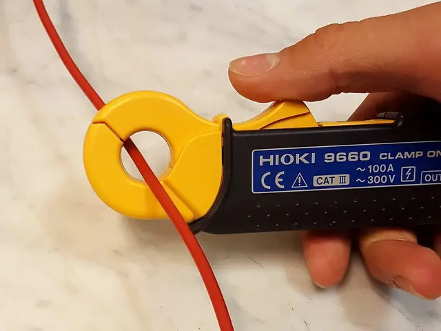
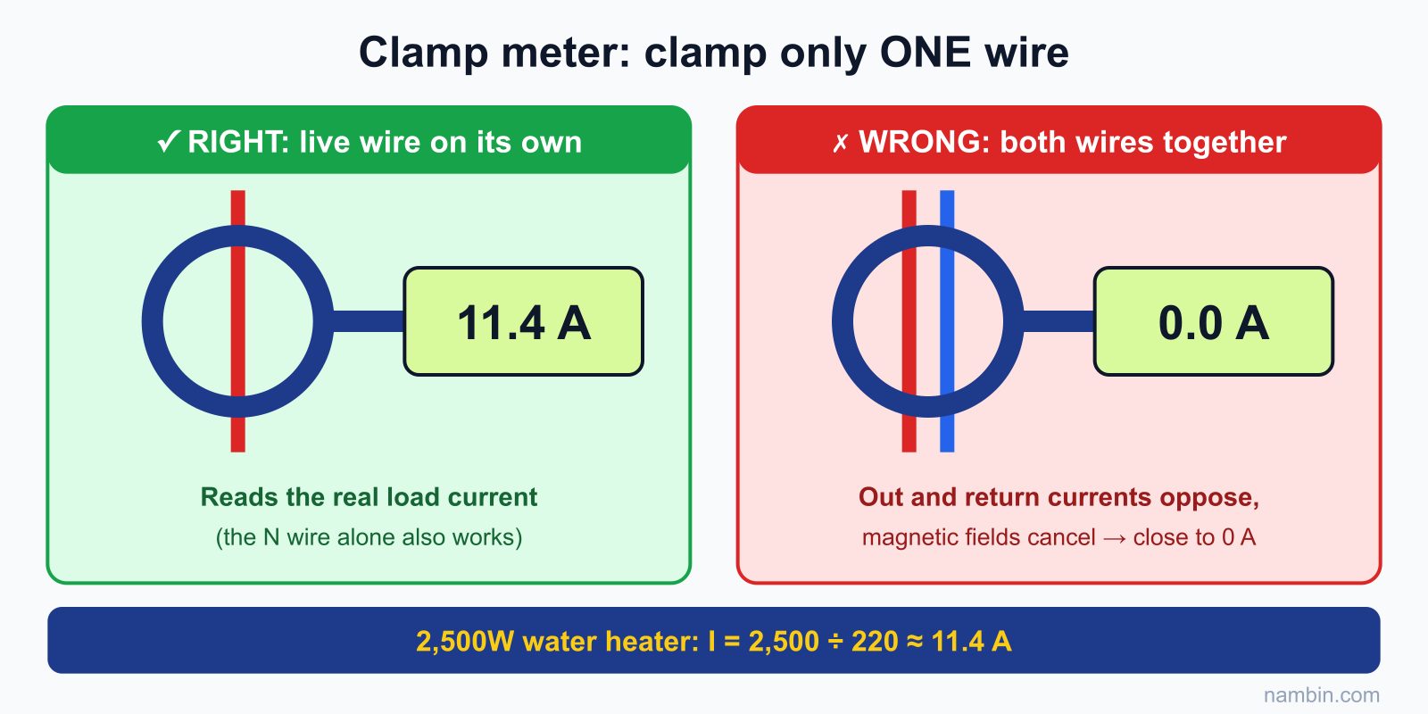
This roadmap step includes the clamp meter because beginners often want to measure current through the A socket of the multimeter — which means cutting the wire and connecting the meter in series, making a short circuit very easy. A clamp meter closes around a single wire (only the live or only the neutral) and reads the current. If you clamp the whole two-core cable, the magnetic fields of the two wires cancel each other and the reading is close to 0A. Example: clamping the live wire of a running 2,500W water-heater circuit and reading about 11A is correct (2,500 / 220 ≈ 11.4A). Reading real current is the basis for calculating loads in the next step.
Worked case: a kitchen outlet that keeps cutting out
A client in an apartment reports that the kitchen outlet sometimes loses power, and the indicator light on the rice cooker flickers when it is plugged in. Other rooms are fine. Here is how you use the meter to narrow the fault down.
Measure with power on to observe the symptom
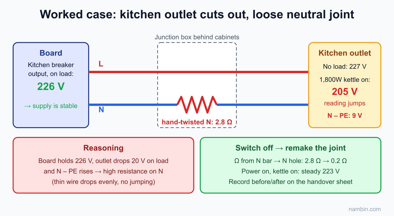
Check the meter on a living-room outlet: 228V. Measure the kitchen outlet with no load: live – N 227V, N – PE 0.4V — normal. Plug in a 1,800W electric kettle and measure again: live – N drops to 205V and keeps jumping, N – PE rises to 9V. At the distribution board, the output of the kitchen circuit breaker stays at about 226V under load.
Reasoning
The voltage at the board is stable, but at the outlet it drops by 20V under load and N – PE rises: there is abnormally high resistance on the neutral wire between the board and the outlet — most likely a loose joint. If the wire were simply too small, the drop would be even and steady, without the reading jumping.
Switch off, measure and repair
Switch off the kitchen breaker, lock out and test again following the procedure. Open the junction box behind the kitchen cabinets and you find the neutral joint twisted by hand and wrapped in tape, with blackened copper. Measure Ω from the neutral bar in the board to the N hole of the outlet: 2.8 ohms — far too high for a few metres of wire. Remake the joint with a proper connector and measure again: 0.2 ohms. Switch on, plug in the kettle: live – N 223V, steady. Record the before and after readings on the handover sheet for the client.
Common mistakes when using a meter
- Measuring voltage while set to Ω or A. Signs: a "crack", the display goes dead, the probes burn. Cause: forgetting to turn the dial after the previous measurement. Prevention: look at the dial and the probe sockets before every time you touch the circuit.
- Concluding "it's dead" when the meter battery is flat or HOLD is on. Signs: the number never changes, or 0V everywhere. Prevention: always test on a known live source before and after.
- Holding the probes too close to the metal tips. If a finger slips onto the tip, you get a shock. Always keep your fingers behind the finger guard.
- Measuring current through the A socket on a 220V circuit. Use a clamp meter instead of cutting the wire and inserting the meter.
- Probes without CAT III/IV tip shrouds when measuring inside a board. A long probe tip can touch two busbars at once and cause a short. Fit the shrouds so only a few mm of tip is exposed.
Looking after your meter
- Replace the battery when the display shows it is low — a low battery gives wrong readings.
- Check the probes before use: if the insulation is cracked or the core is exposed, replace them immediately.
- When you finish, turn the dial to OFF or V~ so that next time you do not accidentally measure on the wrong range.
- When replacing the internal fuse, use exactly the fuse type printed on the meter. Replacing it with copper wire or a cheap fuse removes the last layer of protection.
- Store the meter in its case, away from moisture. If the meter has been dropped hard or its case is cracked, check it on a known source before trusting it.
Frequently asked questions
Can I use an analogue (needle) meter?
Yes, and some electricians still like them because you can see the needle's trend. But analogue meters are hard to read accurately, are easily damaged on the wrong range, and most cheap models carry no CAT rating. Beginners should start with an auto-ranging digital meter rated CAT III 600V.
Live – N reads 0V. Does that definitely mean it is safe?
Not necessarily. You must also measure live – PE and N – PE, and test the meter on a live source before and after. With a lost neutral, live – N can be 0V while both wires are at 220V to earth.
Why do the meter and the tester pen give different results on the same outlet?
The pen reacts to the voltage to earth through your body, while the meter measures the difference between its two probes. A neutral broken upstream can make the pen light up in both holes. When the two tools disagree, trust a meter measurement that covers all three pairs and keep narrowing down.
The continuity test beeps but the appliance still does not work. Why?
The wire may be continuous but have a high-resistance joint, or the fault may be in the appliance itself. Switch to the Ω range to read the value, measure section by section, and measure the voltage at the appliance under load.
Should I buy the cheapest meter to learn on first?
You can use a cheap one to practise measuring batteries and resistors on the bench. But once you start measuring 220V mains, use a meter and probes clearly marked CAT III. As a 2026 reference price, digital meters that meet this requirement range from a few hundred thousand VND to over 1 million VND (very roughly 10–45 US dollars) depending on the model.
Practice exercises and self-check
- Why must you never measure voltage with the red probe in the A socket?
- What does it mean if both holes of an outlet read 220V to earth?
- Practice: measure and record the voltage of every outlet in one room; check the continuity of an extension lead.
Extended exercises
- Make a table of every outlet in the house: location, live – N, live – PE, N – PE (if there is PE). Mark any outlet with unusual readings.
- Unplug an electric kettle or iron, measure the resistance between the two plug pins and compare it with the value calculated from R = U² / P.
- Measure the resistance between each plug pin and the metal case of an appliance with a metal body.
- If you have a clamp meter, measure the current of a running appliance and compare it with P / U.
Self-assessment criteria
- Pass: before every measurement you check the dial and the probe sockets yourself, without being reminded.
- Pass: your measured heating-element resistance is within about 10–15% of the calculated value.
- Pass: you can explain why clamping the whole two-core cable reads close to 0A.
- Not yet: you have measured Ω or continuity on a live circuit, or concluded "it's dead" without testing the meter on a live source.
Next in the roadmap is the step Reading diagrams & calculating household loads: the numbers you have just measured — real current with the clamp meter, voltage drop between board and outlet — will be used to calculate power and choose wire cross-sections and circuit breakers for each circuit. The continuity and resistance measurements in this lesson are also a mandatory part of the pre-energising test procedure in the circuit installation exam (step 7).