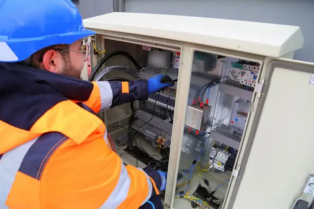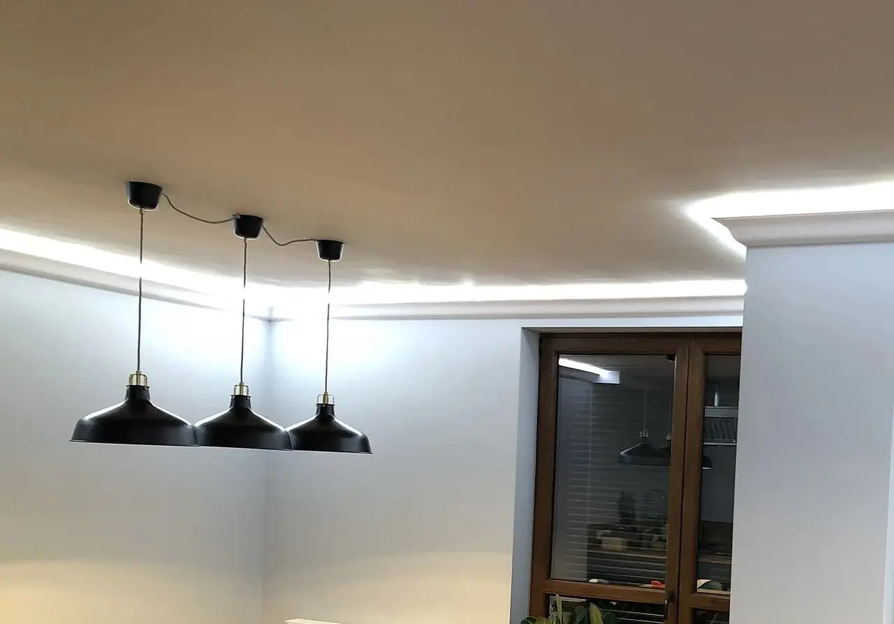
A client wants a soft glow along the ceiling cove in the living room and bright light on the kitchen worktop under the wall cabinets. LED strip looks easy: peel, stick, plug in. Strips fitted that way often show the same problems a few months later: a dim, yellowish far end, adhesive letting go in the heat, a driver overheating inside a closed ceiling, or flicker once a dimmer is added.
This guide covers the job step by step: planning, choosing 12 V or 24 V strip, sizing the driver, feeding long runs evenly, wiring the mains side safely, cutting and joining, mounting in aluminium channel, and testing.
Scope of this guide. This article is for trainee and working residential electricians on single-phase 230 V / 50 Hz supplies, as used in Vietnam. The low-voltage side of a strip (12 V or 24 V DC) is low risk to touch, but the driver is connected to mains voltage, and work on fixed wiring must only be done by a competent person following current Vietnamese regulations and the manufacturer's instructions. Numbers marked for reference are typical values or worked examples only; the datasheet and label of the actual strip and driver always come first.
How an LED strip system works
A typical low-voltage strip installation has five parts:
The strip. A flexible circuit board with LEDs and small resistors. Two copper tracks, + and −, run its whole length, and the LEDs sit in short segments connected across them in parallel. That is why you can cut between segments and the rest still works.
The driver (LED power supply). For most strips a constant-voltage unit turning 230 V AC into 12 V or 24 V DC. Its output voltage must match the strip exactly.
The mains feed. A switched supply from a lighting circuit, with the switch in the line (live) conductor and the circuit protected by its MCB and RCD.
The low-voltage cable from driver to strip.
The mounting. Ideally an aluminium channel with a diffuser.
Almost every strip fault comes from one of these five parts.
Step 1: Plan the job with the client
Walk the room with the client and agree on:
Where the light goes. Measure every run (cove, each wall cabinet, shelves, stairs) and note corners and breaks.
Colour temperature. Warm white (around 2700–3000 K) for living rooms and bedrooms, neutral or cool white for kitchens. Match the room's other lights.
Brightness. A cove that washes the ceiling needs far less light than a worktop. Brighter strips need a bigger driver and more care with heat.
Control. Wall switch, dimmer, remote, cabinet sensor or Wi-Fi controller. Decide now, because it decides the driver (see "Dimming and control").
Driver location. Dry, ventilated and reachable later: above a cabinet, at an access hatch in the false ceiling, or in a ventilated enclosure. Never seal a driver into a ceiling or wall.
Wet places. Near a sink, in a bathroom or outdoors, use a strip with a suitable IP rating and keep the driver rated for, or outside, that location.
Write down the length of each run; you need it for the next steps.
Step 2: Choose 12 V, 24 V or a mains-voltage strip
12 V and 24 V strips
For the same power, a 24 V strip draws half the current of a 12 V strip, so there is much less voltage drop and it can usually run further from one feed point.
12 V suits short runs (one cabinet or shelf) or clients with existing 12 V parts.
24 V suits long runs such as coves, and is the easier choice for most new installations.
12 V strips usually have shorter cutting segments, which helps on very short pieces (Figures 1 and 2).
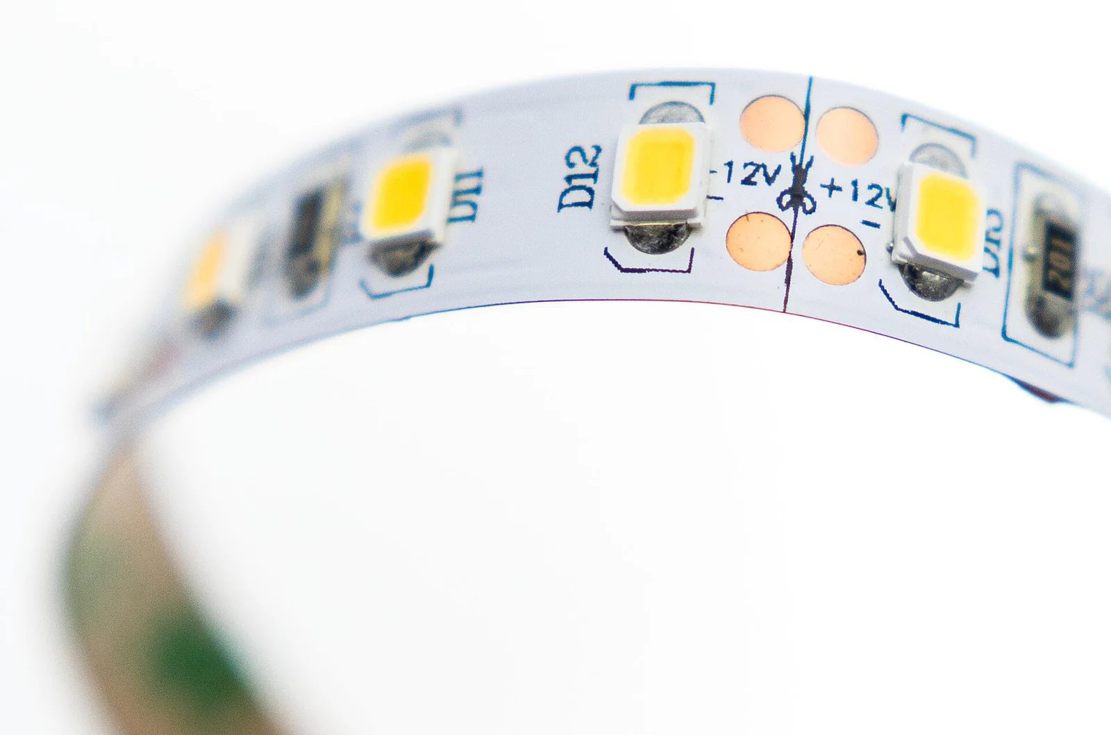
Figure 1. A 12 V LED strip at a cut point: a printed line with a scissors symbol runs between two pairs of copper pads, with 12V and polarity marks beside them. Cut only on this line, and solder or clip feed wires to these pads. (Photo: MickelPL, Wikimedia Commons, CC BY-SA 4.0)
Mains-voltage (230 V) strips
Some strips run directly from 230 V through a rectifier plug. Every part of them is at mains voltage, they can only be cut at the long intervals the maker marks, and a damaged cover or wrong end cap can expose live copper. In homes, prefer low-voltage strip, especially within reach (under cabinets, stairs). If a client insists on 230 V strip, use only the maker's connectors and end caps, never cut it while connected, and follow its instructions exactly.
Read the strip's label
Find these on the reel label or datasheet:
Rated voltage (12 V or 24 V DC)
Power per metre (W/m)
Maximum length per feed (often given as "max run" or "max length")
Cutting interval
IP rating and colour temperature
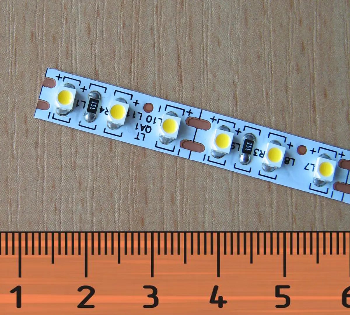
Figure 2. An SMD 3528 strip (120 LEDs per metre, according to the uploader) beside a centimetre ruler. Each segment between copper pads has three LEDs and one resistor and is roughly 2.5 cm long; groups of three LEDs like this are typical of 12 V strips. (Photo: Andrey Gvrv, Wikimedia Commons, CC BY-SA 3.0)
Step 3: Calculate the load
The total power of a run is simply:
Total power (W) = power per metre (W/m) × length (m)
Then the current the driver must supply is:
Current (A) = total power (W) ÷ strip voltage (V)
Example: the cove in the living room is 9 m long, and the client chose a strip rated at 9.6 W/m (a common catalogue value; check your product). Total power = 9.6 × 9 = 86.4 W. At 24 V that is 86.4 ÷ 24 = 3.6 A. At 12 V it would be 7.2 A, twice the current through the same copper.
Reference table: power and current
The current column is pure arithmetic (I = P ÷ V). The driver column uses the margin rule in Step 4 and is for reference.
Total strip load | Current at 12 V | Current at 24 V | Smallest driver if loaded to about 80% (for reference) |
|---|---|---|---|
24 W | 2.0 A | 1.0 A | 30 W |
48 W | 4.0 A | 2.0 A | 60 W |
72 W | 6.0 A | 3.0 A | 90 W |
96 W | 8.0 A | 4.0 A | 120 W |
144 W | 12.0 A | 6.0 A | 180 W |
In practice, choose the next standard driver size up.
Step 4: Choose the driver
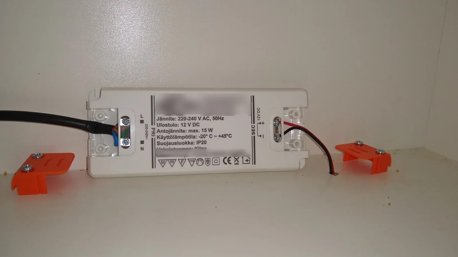
Figure 3. A 12 V constant-voltage LED driver during wiring, with its orange terminal covers removed. The Finnish label gives the input (220–240 V AC, 50 Hz), output (12 V DC), maximum load (15 W) and IP20 (dry indoor use only). Mains L and N enter on the left; red (+) and black (−) wires go to the strip on the right. Refit both covers before switching on. (Photo: Dmitry G, Wikimedia Commons, CC BY-SA 3.0; cropped from a collage, brand blurred)
Check each of these on the driver label (Figure 3):
Output voltage matches the strip. A 24 V driver will quickly destroy a 12 V strip; a 12 V driver barely lights a 24 V strip.
Constant voltage. Constant-current drivers (rated in mA with a voltage range) are for LED modules and downlights, not ordinary strips, unless the strip maker says otherwise.
Power with a margin. Many manufacturers and installers recommend loading a driver to about 80% of its rating or less (for reference; follow the datasheet). The 86.4 W cove above needs at least about 108 W, so a 120 W or 150 W unit. A driver at full load in a hot ceiling ages fast and may flicker or shut down.
Input covers 230 V / 50 Hz, e.g. "220–240 V AC, 50 Hz" or "100–240 V AC, 50/60 Hz".
IP rating. IP20 means dry indoor places only. For damp places use a suitably sealed driver, or keep the driver dry nearby and run only low-voltage cable into the damp area.
Earth. Double-insulated (Class II) drivers have no earth terminal. If the driver has an earth terminal (Class I), connect the circuit's earth conductor to it.
Dimming type, if needed (see below).
Two or three smaller drivers, each close to its run, are often better than one large driver: shorter DC cables, less voltage drop, and a failure darkens only part of the room.
Step 5: Plan the feed points to avoid voltage drop
Voltage drop is the usual reason a strip is bright at the start and dim and yellowish at the end. It happens in the strip's own tracks and in the cable from the driver.
Inside the strip
The tracks are thin, so each strip has a maximum length per feed point. Many 12 V strips come on 5 m reels and datasheets often limit one feed to about that length; 24 V versions usually allow longer (for reference; read the datasheet). For longer runs:
Feed both ends, or from the middle.
Feed in parallel: a separate pair of wires from the driver to each section. Never chain reel after reel and feed only the first; its tracks then carry the current for all of them.
Keep polarity the same at every feed point.
In the low-voltage cable
Current flows out and back, so a simple estimate for copper cable is:
Voltage drop (V) ≈ 2 × L × I × 0.0175 ÷ A
where L is the one-way cable length in metres, I is the current in amps, A is the conductor cross-section in mm², and 0.0175 Ω·mm²/m is the approximate resistivity of copper at room temperature. Then compare the drop with the strip voltage.
Example (5 m one-way cable) | Current | Cable | Approx. voltage drop | As % of strip voltage |
|---|---|---|---|---|
60 W at 12 V | 5.0 A | 0.75 mm² | 1.17 V | about 9.7% |
60 W at 12 V | 5.0 A | 1.5 mm² | 0.58 V | about 4.9% |
60 W at 24 V | 2.5 A | 0.75 mm² | 0.58 V | about 2.4% |
60 W at 24 V | 2.5 A | 1.5 mm² | 0.29 V | about 1.2% |
The cures are clear: bigger cable, 24 V, or both. The thin lead supplied on a strip is only for short connections. Installers commonly aim to keep the drop to a few percent so brightness and colour stay even (for reference). Best of all, put the driver close to the strip.
Step 6: Isolate and wire the mains side
The mains side is where the real danger is. Treat it like any other lighting point.
Plan the supply. Feed the driver from a lighting circuit through a switch (or dimmer or controller) in the line conductor. Never use an extension lead hidden in a ceiling or cabinet as a permanent supply.
Isolate. Switch off and lock off (or tag) the circuit's MCB. Prove your tester on a known live source, test line–neutral, line–earth and neutral–earth, then prove the tester again.
Joints in an enclosure. Mains joints go inside a junction box or the driver's terminal compartment, with correctly rated screw or lever terminals. No twisted, taped joints in the ceiling.
Connect the input. Line to L, neutral to N, earth to the earth terminal if present. Clamp the cable in the cord grip.
Refit the terminal covers before power is applied. Figure 3 shows a driver with its orange covers removed during wiring; they must go back on.
Fix the driver with screws, with air space around it. Never bury it in insulation or wrap it.
If the lighting circuit has no RCD protection or the wiring looks doubtful, tell the client and recommend an inspection.
Step 7: Cut, join and connect the strip
Cutting
Cut only on the marked cut line, normally a line through the middle of a pair of copper pads, often with a scissors symbol (Figure 1). Cutting anywhere else breaks a segment, and that segment will stay dark. Use sharp scissors and cut straight.
Joining
There are two common methods:
Clip-on (solderless) connectors. Quick and tidy, but only use connectors made for your strip's width and type, push the strip fully in, and check that the contacts sit squarely on the pads. A loose clip connector is a common cause of flicker and sections going out.
Soldering. More reliable, especially for feed points. Tin the pads and the wires first, keep the iron on each pad only briefly, and make a neat joint without bridging + and −. Cover the joint with heat-shrink sleeve and fix the cable so it cannot bend the joint back and forth.
On a waterproof strip with a silicone coating, remove the coating carefully at the pads, then re-seal the joint with the maker's end caps and a suitable sealant, or the water protection is lost.
Polarity
Check + to + and − to − at every joint, following the marks on the strip and driver. A simple single-colour strip connected backwards usually just stays dark; colour-changing or addressable strips can be damaged, so check before switching on.
Corners
Do not fold the strip sharply across its width on a corner; this can crack the tracks. Use a corner connector, or cut the strip at the corner and join the two pieces with a short pair of wires.
Step 8: Mount the strip in aluminium channel
The strip's adhesive tape is not a full mounting system, especially in Vietnam's heat and humidity; on dusty or painted surfaces it often peels within months. An aluminium channel:
Carries heat away, which higher-power strips need, or the LEDs age faster and shift colour.
Looks neat: the strip sits straight and a diffuser turns the dots into a smooth line.
Protects the strip from dust, cloths and fingers.
How to mount:
Cut the channel with a fine-tooth saw and deburr it.
Fix it with screws or the maker's clips.
Clean and dry the inside, then press the strip in along its whole length without stretching it.
Lead the wires out through an end cap or a grommeted hole, never over a sharp edge.
Fit the diffuser and end caps.
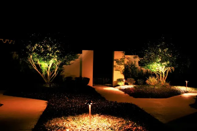
In a cove, hide the strip from view so the light washes across the ceiling (cover image). Under a cabinet, a strip close to the wall mainly lights the splashback (Figure 4); mounting it further forward puts more light on the worktop.
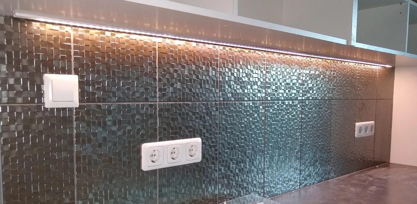
Figure 4. The finished job: a strip fixed under the wall cabinets lights the tiled splashback. According to the photographer, the strip is mounted on a heatsink attached to the underside of the shelf; a strip mounted closer to the front edge would put more light on the worktop. (Photo: Dmitry G, Wikimedia Commons, CC BY-SA 3.0; cropped from a collage)
Step 9: Test and hand over
Before closing anything, switch on and check every section lights evenly.
Measure DC voltage with a multimeter at the driver output, then at the far end of each run, lights on. A noticeably lower far-end reading points to cable size, feed points or joints.
Measure current with a DC clamp meter if you have one and compare it with your calculation.
Run it for a while (for example 30 minutes). The driver may be warm; if it is too hot to keep your hand on, it is overloaded or badly ventilated.
Test the control over its full range.
Hand over: show the client where the driver is and which MCB feeds it, and leave the datasheets.
Dimming and control
The dimming method must match the driver. Mixing them is the main cause of flicker and buzzing.
Mains wall dimmer (phase-cut). Only with a driver marked dimmable with that dimmer type (leading- or trailing-edge). An ordinary driver behind one may flicker, buzz or fail.
Low-voltage PWM controller. Fitted between an ordinary constant-voltage driver and the strip, often with a remote or Wi-Fi. Size it for the strip current.
0–10 V or DALI. Needs a driver with that input and correct control wiring.
RGB or tunable-white strips have extra conductors and need a matching controller; check the pin order before connecting.
Troubleshooting common strip faults
Symptom | Likely causes | What to check |
|---|---|---|
Far end dimmer or more yellow than the start | Voltage drop in strip or cable | DC voltage at start and end; feed both ends or in parallel; larger cable; move driver closer; consider 24 V |
One section dark, rest working | Bad cut, cracked track at a sharp bend, failed joint or connector | Look and press at joints; measure voltage either side of the dark section |
Whole strip dark | No mains to driver, driver protection tripped, reversed polarity, open joint at first feed | Mains at driver input; DC at output; polarity at the first joint |
Flicker or blinking | Driver overloaded or overheating, loose clip connector, incompatible dimmer | Load versus driver rating; ventilation; reseat or solder joints; dimmer and driver compatibility |
Driver buzzing or very hot | Overload, poor ventilation, wrong dimmer | Load calculation; move or enlarge driver; correct dimming type |
Strip falling off | Adhesive on dusty or uneven surface, heat | Mount in aluminium channel with mechanical fixing |
LEDs fail early or change colour | Strip running too hot, over-voltage, wrong driver voltage | Driver output voltage; use channel; check power per metre suits location |
Safety checklist
☐ Circuit isolated at the MCB, locked off or tagged, and proved dead with a tester checked before and after.
☐ Switch (or controller) breaks the line conductor, not the neutral.
☐ All mains connections inside a proper enclosure or the driver's terminal compartment, with terminal covers refitted.
☐ Driver output voltage matches the strip voltage; driver is constant-voltage.
☐ Driver loaded with a margin (about 80% or less of its rating, for reference; follow the datasheet).
☐ Driver dry, ventilated, reachable, and earthed if it has an earth terminal.
☐ Strip and driver IP ratings suit the location (kitchen sink, bathroom, balcony, outdoors).
☐ Polarity correct at every joint; joints insulated and strain-relieved.
☐ Long runs fed from both ends or in parallel; low-voltage cable sized for the current.
☐ Voltages measured at driver and far end; driver temperature checked after a test run.
☐ Dimmer, controller and driver are a compatible combination.
☐ Client told where the driver is and which MCB feeds it.
Frequently Asked Questions
Can I plug an LED strip into a normal wall socket?
Plug-in kits with their own adapter are made for that. For a permanent ceiling or cabinet installation, feed a fixed driver from the lighting circuit through a switch, with connections in a proper enclosure.
How long can one LED strip run be?
Check the datasheet's maximum length per feed. It is often around one reel length, with 24 V allowing longer runs than 12 V (for reference). Beyond that, feed both ends or in parallel.
Why does the end of my strip look dimmer and more yellow?
Almost always voltage drop. Measure DC voltage at both ends, then feed both ends or in parallel, use thicker cable, move the driver closer or change to 24 V.
Do I really need an aluminium channel?
Low-power strips in a cool, clean place can go directly on a clean surface. For brighter strips, warm places and a neat finish, a channel is strongly recommended.
Can I use LED strip in a bathroom or outdoors?
Yes, if strip, connectors and driver have suitable IP ratings and the bathroom zone rules are followed. Keeping the driver dry, outside the wet area, reduces risk.
Can I dim any LED strip with a normal wall dimmer?
No. It needs a driver marked dimmable with that dimmer type. Otherwise use a low-voltage PWM controller after an ordinary driver.
Practice Exercises
Load and driver. A kitchen has three cabinet runs of 1.2 m, 1.5 m and 0.9 m, using a 24 V strip rated at 10 W/m. Calculate the total power, the current, and the smallest standard driver you would choose if you load it to about 80%. (Answer: 3.6 m × 10 W/m = 36 W; 36 ÷ 24 = 1.5 A; at least 36 ÷ 0.8 = 45 W, so a 50 W or 60 W driver.)
Voltage drop. A 12 V strip draws 4 A and the driver is 6 m away, connected with 0.75 mm² cable. Estimate the voltage drop and say whether you would accept it. (Answer: 2 × 6 × 4 × 0.0175 ÷ 0.75 ≈ 1.12 V, about 9% of 12 V; too much. Use thicker cable, move the driver closer, or change to 24 V.)
Feed layout. Sketch a 10 m cove with the driver at one corner hatch, fed so both halves get an even voltage.
Fault-finding. An under-cabinet strip flickers only when dimmed. What do you check on the driver and dimmer labels, and in what order?
Hands-on. On a bench, cut a strip at a marked line, solder and heat-shrink a feed pair, connect it to a driver (covers fitted, protected test supply) and record the voltage at both ends.