Replacing a ceiling light is one of the most common jobs a residential electrician is asked to do. A family wants a modern LED flush-mount in place of an old fluorescent fitting. The electrical part usually involves only two or three conductors, so the job looks easy. The real risks are elsewhere: a circuit you thought was off, a switch that breaks the neutral instead of the live, a metal fitting with no earth, or a heavy fitting held up by one plastic wall plug in a gypsum ceiling.
This guide follows the job the way a careful electrician does it: isolate and prove dead, take down the old fitting, identify each conductor, check the ceiling and the weight, fix the bracket, connect, earth, deal with LED drivers, then test and hand over. It is written for Vietnamese homes on a single-phase supply of nominally 220–230 V, 50 Hz.
Scope and safety. This article covers replacing an existing ceiling light point with a pendant or surface (flush-mount or semi-flush) fitting. It does not cover recessed downlights, new circuits or work inside the distribution board. Mains voltage can kill. Learners should do this job only under the supervision of a qualified electrician, and anyone who finds damaged, burnt or confusing wiring should stop and get a qualified electrician to inspect the circuit. Numbers here are for reference only; always follow the fitting manufacturer's instructions and the rules that apply where you work.
Before you start: survey, tools and materials
Ask the client to show you the new fitting (still in its box), the switch and the distribution board, and check four things:
Weight and fixing method of the new fitting, usually printed on the box or in the leaflet.
Ceiling type: concrete slab, gypsum board on a metal frame, timber, or PVC panels.
Fitting class: metal-bodied with an earth terminal (Class I) or double insulated (Class II), and whether there is an earth conductor at the ceiling.
Switch type: ordinary, dimmer, timer or "smart" switch. Some LED fittings do not work properly with dimmers or with smart switches that have no neutral.
Item | Purpose and notes |
|---|---|
Two-pole voltage tester or multimeter | Proving dead; check it on a known live source before and after |
Non-contact voltage detector (optional) | A quick warning check only, never proof that a conductor is dead |
Insulated screwdrivers, wire stripper, side cutters | Removing the old fitting and preparing conductor ends |
Stable stepladder, head torch | Safe working position and light; never stand on chairs or tables |
Hammer drill and bits, safety glasses, dust mask | Drilling fixing holes, especially in concrete |
Wall plugs, anchors and screws suited to the ceiling | Fixing the bracket; the plugs supplied in the box are not always suitable |
Screw terminal strip or lever connectors, cord-end ferrules | Making connections; rated for the voltage, current and conductor size |
Lock-off device or tape, warning tag, marker | Keeping the breaker off and labelling conductors |
Step 1: Isolate the circuit and prove it dead
Turning off the wall switch is not isolation. In many Vietnamese houses the switch has been wired to break the neutral instead of the live, so the lampholder can still be live with the switch off. The ceiling point may also carry a permanent live looping on to other lights.
Find the breaker. Switch the light on, then switch off the breaker you think feeds it; the light should go out.
Use the main breaker when in doubt. If the breakers are single-pole, the wiring is old or you are unsure which breaker feeds the point, switch off the main breaker. In older installations a single-pole breaker may be on the wrong conductor, and lighting circuits sometimes share a neutral with another circuit. Warn the client first (fridge, router, water pump).
Lock it off. Fit a lock-off device or, if impossible, tape the breaker off and hang a tag such as "Electrician working – do not switch on". Tell everyone in the house.
Prove your tester on a known live source, such as a working socket outlet.
Test at the light point, without touching the terminals: live–neutral, live–earth, neutral–earth, and every extra conductor against the others, with the wall switch both on and off. There should be no voltage on any combination.
Prove your tester again on the same live source to confirm it did not fail during the test.
If you get any reading, even a low or unstable one, stop and find out why. It may be induced voltage, a second supply or a borrowed neutral.
Step 2: Remove the old fitting
Set the ladder directly under the light; ask a helper to hold heavy fittings.
Remove lamps, shades and diffusers first, then undo the fitting from the ceiling while supporting its weight. Never let a fitting hang from its supply wires.
Photograph the connections before undoing anything. If there are more than two or three conductors, label each with tape (for example "L-loop", "SW", "N", "E").
Release the conductors and inspect the ends. Heat-damaged insulation is common above old halogen and incandescent fittings. If the damage goes beyond a short length you can cut back, the cable needs replacing; plan that with a qualified electrician.
Step 3: Identify live, neutral, earth and switched live
A simple light point usually has a switched live from the switch and a neutral, plus an earth if the circuit has a protective conductor. With the "loop-in" method, the permanent live, neutrals and switch cable all meet at the ceiling, so you may find several cables.
The IEC colour code, now the usual standard for new installations in Vietnam, is brown for line, blue for neutral and green-and-yellow for earth. In real houses you will meet red and black pairs, two conductors of the same colour, and blue used as a live. Colour is a clue, never proof. For the different colour codes and how to identify conductors by testing, read our guide Electrical Wire Color Codes: How to Identify Live, Neutral and Earth Wires Safely.
What you find at the ceiling | What it probably is | How to confirm |
|---|---|---|
Two conductors only (e.g. red and black) | Switched live and neutral | Power off: continuity test back to the switch terminals (see below) |
Green-and-yellow, or bare copper in green-and-yellow sleeving | Protective earth | Low-resistance continuity to the earth terminal of a nearby socket outlet or the earth bar |
Several cables with conductors joined in groups | Loop-in point: permanent live, neutrals, switch drop | Photograph and label; reconnect in exactly the same groups |
The old lamp stayed live with the switch off | Switch breaks the neutral, not the live | Correct the wiring at the switch; do not just swap conductors at the light |
Finding the switched live with the power off. With the circuit isolated and proved dead, set your multimeter to continuity. With the switch plate removed but the switch still connected, use a long test lead (a wander lead) to test from each ceiling conductor to each switch terminal. The conductor that reads continuity to one switch terminal all the time, and to the other only when a helper turns the switch on, is the switched conductor. It is the switched live only if the switch's other terminal is fed from the line; if it is fed from the neutral, the switch is breaking the neutral.
If the switch is breaking the neutral, correct it so it breaks the line conductor. Otherwise the lampholder stays live, and the next person changing a lamp could get a shock.
Step 4: Check the ceiling and the weight
Check the weight, then look through the existing hole with a torch to see what the ceiling is made of. Most Vietnamese townhouses and apartments have either the bare reinforced concrete slab or a suspended gypsum board ceiling (trần thạch cao) on a light metal frame below the slab. Gypsum board on its own is weak; screws and plugs pull out of it under load.
Ceiling type | Light fittings (small LED flush-mount, simple pendant) | Heavier fittings (large glass pendants, chandeliers) |
|---|---|---|
Concrete slab | Plastic wall plugs of the right size with matching screws, drilled with a hammer drill | Metal expansion anchors or a ceiling hook rated for the load; never plastic plugs alone |
Gypsum board on metal frame | Cavity anchors (spring toggles, hollow-wall anchors) within their rated load; better, screw into a frame member | Never hang from the board. Add a support across the frame, or hang from the slab above with threaded rod or a rated hanger |
Timber ceiling | Wood screws into solid timber | Screws or a hook into a joist or fixed noggin, not thin boards |
PVC panel ceiling | Fix through to the battens behind, not into the panel | Fix to the structure above; panels carry no weight |
For reference only. Always use each anchor manufacturer's rated load with a generous safety margin. When you are unsure, treat the fitting as heavy.
In concrete slabs, the cable to the light point often runs in conduit inside the slab. See which side the conduit enters the hole and keep your drill holes away from that line, drilling only as deep as the plug needs.
On pendants, the weight must hang from the hook or canopy fixing, and the flex must be held by the cord grips in the canopy and lampholder so no weight pulls on the terminals.
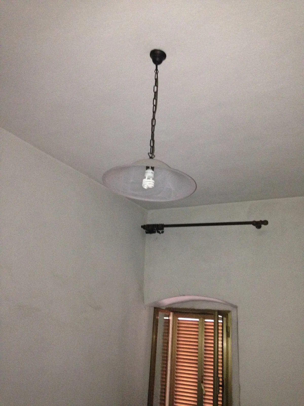
Figure 1. A pendant light with a frosted shade hanging on a chain from a small dark canopy on a plain painted ceiling. The chain, not the electrical flex, must carry the weight, and the fixing above the canopy must be rated for it. (Photo: Antonio Mette, Wikimedia Commons, CC BY-SA 4.0)
Step 5: Fix the mounting bracket
Most surface fittings come with a steel mounting bar or plate that is fixed to the ceiling first; the fitting body then screws or clips onto it.
Hold the bracket centred over the cable entry and mark the holes. The cable must pass through without being pinched.
Check the fitting will sit straight; long fittings usually run parallel to a wall.
Drill using the right method for the ceiling, wearing safety glasses and, for concrete, a dust mask.
Fix the bracket and pull it firmly by hand. It must not move.
Protect conductors from sharp metal edges with a grommet or sleeve.
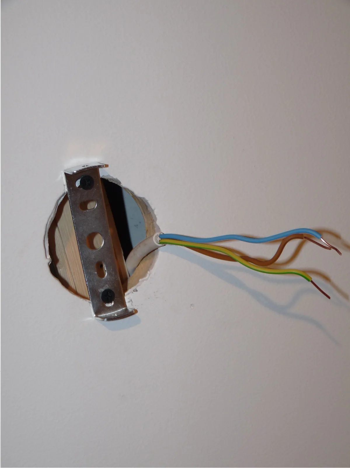
Figure 2. A steel mounting bracket screwed across a round cable hole in a white ceiling, with the blue, brown and green-and-yellow cores of the supply cable brought out to the side, ready for connection. (Photo: Dmitry G, Wikimedia Commons, CC BY-SA 3.0; cropped from a larger image)
Step 6: Make the connections
Connections must be made inside an enclosure: the terminal compartment of the fitting or a proper junction box. Twisting conductors together and wrapping them in tape, still common in older houses, is not acceptable for new work. A loose joint can overheat in a closed canopy.
Most fittings come with a small screw terminal strip marked L, N and the earth symbol; lever connectors are also widely used. Check that any connector is rated for the mains voltage, the circuit current and the size and type (solid or stranded) of conductor.
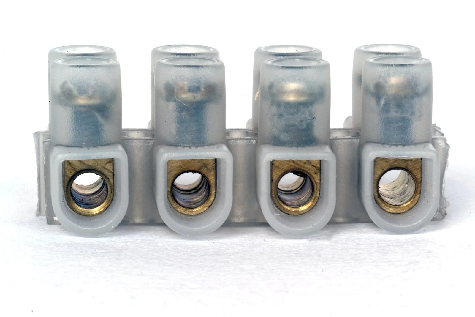
Figure 3. A four-way screw terminal strip (connector block) with a clear plastic body and brass clamping tubes. Each conductor goes fully into its tube and is clamped by the screw; no bare copper should be visible outside the plastic. (Photo: VSchagow, Wikimedia Commons, CC BY-SA 4.0)
Cut damaged ends back to clean copper. Strip only what the terminal needs, often about 8–10 mm (for reference; check the strip length marked on the connector).
On stranded pendant flex, fit cord-end ferrules or twist the strands neatly. One stray strand touching a metal body can make the fitting live.
Connect the switched live to L, the neutral to N and the earth to the earth terminal. At a loop-in point, reconnect the other conductors in exactly the groups shown in your photo.
With screw (E27/E14) lampholders, the live must reach the centre contact and the neutral the screw shell; correct L and N connections at the fitting give you this.
Tighten each screw firmly on copper, not insulation, then pull each conductor gently. If it moves, redo it.
Fold the conductors into the canopy so they are not trapped and stay clear of hot lampholders and driver cases.
Step 7: Earthing metal (Class I) fittings
A Class I fitting has exposed metal parts protected by the earth conductor: if a live conductor touches the metal, the fault current flows to earth and the breaker or RCD disconnects the supply. It has an earth terminal marked with the earth symbol. A Class II fitting is double insulated, marked with a square inside a square, and is not earthed.
Situation | What to do |
|---|---|
Class I fitting, earth present | Connect the earth and check the earth terminal is connected to the metal body and bracket |
Class I fitting, no earth at the ceiling | Do not install it as it is. Choose a Class II fitting, or have a qualified electrician run an earth conductor. An RCD adds protection but does not replace the earth |
Class II fitting, earth present | Do not connect it to the fitting. Terminate it in its own connector, insulated, for future use |
Any fitting | Never join the earth terminal to the neutral as a "substitute earth" |
Many older Vietnamese houses have no earth at lighting points. Tell the client honestly; a Class II fitting is often the simplest safe choice, and new earth conductors are worth planning with a qualified electrician.
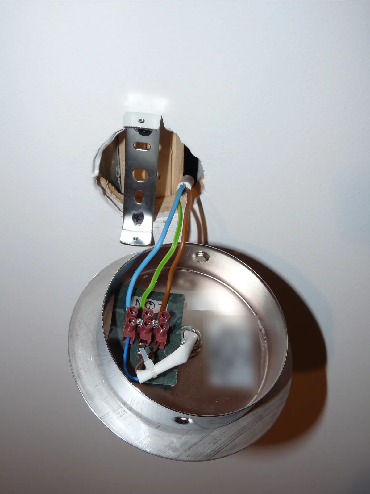
Figure 4. A round metal ceiling fitting being connected below its mounting bracket: the blue, green-and-yellow and brown cores go into a three-way screw terminal block marked with N and the earth symbol, and a short white lead runs to the lampholder. The rating label has been blurred. In real work, support the fitting so it never hangs on the conductors. (Photo: Dmitry G, Wikimedia Commons, CC BY-SA 3.0; cropped, label blurred)
Step 8: LED fittings with a driver
Most modern ceiling lights use LEDs powered by a driver, which converts the mains into the low-voltage DC or constant current the LEDs need.
Input and output. Mains goes only to the input side (marked AC, L/N or with the input voltage range). The output (DC+ / DC−, often red and black leads) goes only to the LED module. Mains on the output side destroys the driver and can be dangerous.
Matching. A replacement driver must match the LED module's required current and voltage range, not just its wattage.
Heat. Do not bury a driver in insulation or press it against the LED board.
Dimmers and smart switches. Use a dimmer only with a fitting marked dimmable and a compatible dimmer. A two-wire smart switch with no neutral may make an LED fitting glow or flicker when off.
Insulation testing. If a qualified electrician carries out an insulation resistance test on the circuit, disconnect the driver first; the test voltage can damage electronics.
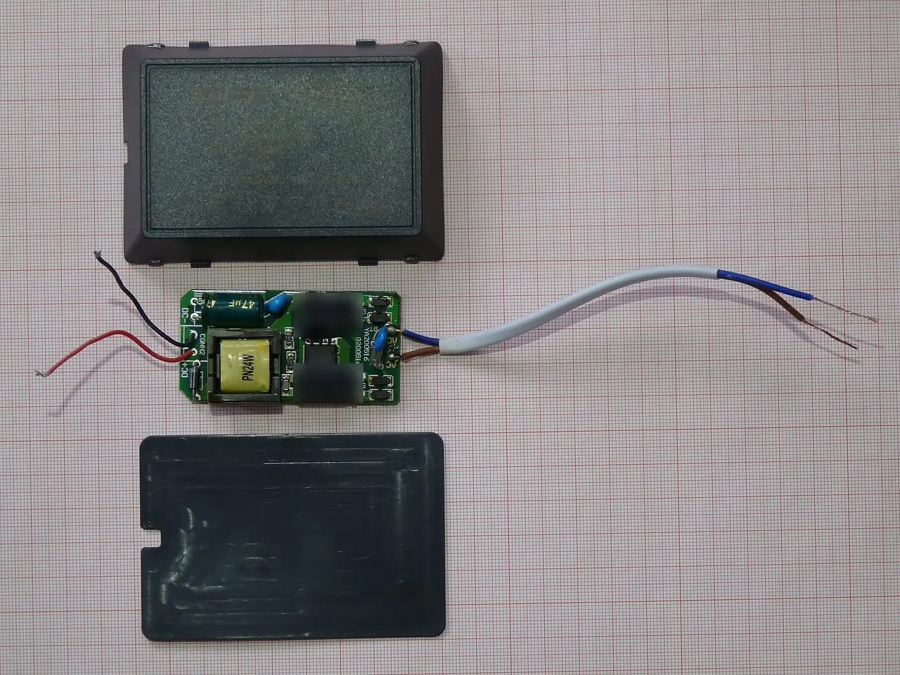
Figure 5. An opened LED driver on graph paper, its circuit board between the two halves of its plastic case. A white cable with blue and brown cores (mains input) leaves on the right; red and black leads (DC output to the LED module) leave on the left. Component brand markings have been blurred. (Photo: Dmitry G, Wikimedia Commons, CC BY-SA 4.0)
Step 9: Mount, test and hand over
Offer the fitting up to the bracket without trapping any conductor and tighten the fixings evenly so the canopy sits flat. Fit lamps no larger than the fitting's marked rating, then the shades or diffuser.
Before switching on: no bare copper or stray strands; earth connected (Class I) or parked and insulated (Class II); fitting firm when pulled gently; for Class I, a low-resistance continuity reading between the metal body and the earth at a nearby socket or the board; tools and offcuts cleared.
Remove your lock and tag, tell everyone, and switch the breaker on.
Operate the switch several times; the light should turn fully on and off.
With the switch off, check with your tester that the lampholder or LED module is not live. If it is, the switch is breaking the neutral: isolate again and correct it.
If there is an RCD or RCBO, check it has not tripped, and press its test button if the client agrees.
Leave the light on for a few minutes; check for flicker, buzzing, smell or heat.
Handover: show the client the light working and which breaker controls it. Explain whether it is dimmable, which lamps to use and that it must be cleaned with the power off. Give them the leaflet and warranty card, and mention anything that needs attention later, such as a missing earth, old insulation or an unlabelled board.
Worked example: LED flush-mount on a concrete ceiling with no earth
An apartment ceiling point has two black conductors and no earth, and the client has bought a plastic round LED flush-mount marked with the Class II symbol. You isolate at the main breaker, prove dead, and find by continuity test that one black conductor goes to the switch, so you mark it with brown tape as the switched live. The old plug holes are crumbling, so you rotate the mounting plate and drill new holes away from the conduit entry, using plastic plugs suited to the light fitting. Because the fitting is Class II, no earth is needed. After switching on, you confirm the LED module is dead with the switch off, and note the missing earth at handover.
Safety checklist
Isolated at the board, not the wall switch; main breaker used when in doubt.
Breaker locked or taped off and tagged; household told.
Tester proved, every conductor tested, tester proved again.
Stable ladder; helper for heavy fittings.
Photo and labels before disconnecting.
Switch breaks the line conductor, not the neutral.
Fixing suits the ceiling and the weight; no weight on conductors or flex.
Rated connectors inside an enclosure; no taped twist joints.
Class I earthed, Class II not earthed, earth never joined to neutral.
LED driver mains on the input side only; dimmer compatibility checked.
Final tests done; client informed of any defects.
Frequently Asked Questions
Can I replace a ceiling light with just the wall switch turned off?
No. The switch may be breaking the neutral, and the ceiling point may carry a permanent live. Always isolate at the distribution board and prove dead with a tester at the light point.
Is a non-contact voltage detector enough to prove the wires are dead?
No. It is a useful warning but can miss voltage or give false readings. Prove dead with a two-pole tester or multimeter checked on a known live source before and after use.
There is no earth at my ceiling. Can I still fit a metal light?
A Class I metal fitting needs an earth. Without one, choose a Class II fitting or have a qualified electrician install an earth conductor. Never connect the earth terminal to the neutral.
Why does my new LED light glow faintly when switched off?
Common causes are a switch breaking the neutral, a two-wire smart switch or illuminated switch passing a tiny current through the driver, or induced voltage on long cables. Check the switch wiring first, because a neutral-switched light is also a safety problem.
When should I call a qualified electrician?
When cable insulation is damaged or burnt, when you cannot confidently identify every conductor, when a metal fitting has no earth, when the board is old or unlabelled, or when you are not sure the ceiling can carry the fitting.
Practice Exercises
Exercise 1: Safe isolation drill. On a training rig under supervision, carry out the full sequence: identify the breaker, lock off, prove the tester, test every pair of conductors, prove the tester again.
Exercise 2: Switched live, power off. On a rig where the conductors at the ceiling are all the same colour, use a multimeter on continuity to identify the switched live and neutral, and label them.
Exercise 3: Choose the fixing. For four fitting-and-ceiling combinations (concrete, gypsum, timber, PVC), write the fixing method and when you would refuse the job as requested.
Exercise 4: Terminal practice. Connect ten solid and stranded conductor ends into a screw terminal strip and lever connectors. Your trainer pull-tests each one.
Exercise 5: Class I or Class II? Read the labels of five light fittings. For each, identify the class, find the earth terminal (if any) and say what you would do if the ceiling had no earth.