The correct way to wire a fan capacitor is: connect the two supply wires to the common wire and the run wire, and connect the capacitor between the run wire and the start wire. A single-phase water pump capacitor is wired on exactly the same principle. To find out which wire is common, run and start, measure the resistance of the three wire pairs with a multimeter: the pair with the highest resistance is run–start, the remaining wire is common, and from the common wire the smaller reading leads to the run winding.
A fan that turns slowly, a fan that only starts when you push the blades by hand, a pump that hums but does not spin — most of these come down to a failed capacitor or to wrong wiring after the capacitor was replaced. This lesson goes from principle to hands-on skill: measuring, wiring, choosing a replacement capacitor and working safely.
By the end of this lesson, you will be able to:
- Explain why the single-phase motor in a fan or a pump needs a capacitor, and where the capacitor sits in the circuit.
- Identify the common, run and start wires of a three-wire motor using only three resistance measurements, and double-check them with a simple sum.
- Wire the capacitor for a pedestal fan, a three-wire ceiling fan and a single-phase water pump from a diagram, and reverse the direction of rotation when it is allowed.
- Recognise a failed fan capacitor from its symptoms and from a microfarad (µF) reading; choose a replacement with the right µF and voltage rating.
- Isolate the power, discharge the capacitor and re-check following a safe procedure before you touch any terminal.
Want to practise with a mentor? Measuring windings, wiring capacitors, float switches and contactors for pumps and fans are practised and graded in the Residential Electrician Level 3 – Master Electrician course (Motors & pumps module).
Why do single-phase fans and pumps need a capacitor?
Single-phase 220V/50Hz power (the standard household supply in Vietnam) only creates a magnetic field that "pulses" back and forth; it does not rotate on its own. Put a rotor in that field and it just sits there and hums — exactly what a fan with a dead capacitor does. To make the motor start by itself, the manufacturer adds a second winding and uses a capacitor to shift the phase of the current between the two windings.
Two windings: the run winding and the start winding
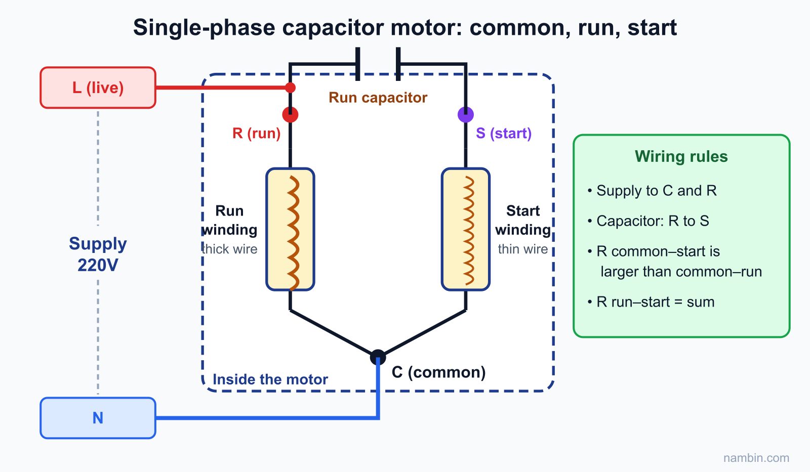
The run winding (also called the main or working winding, marked R or M) is connected straight to the supply. The start winding (auxiliary winding, marked S or A) is connected to the supply through the capacitor. The two windings are placed at an angle to each other on the stator. The current through the capacitor leads in phase, so the magnetic fields of the two windings peak one after the other and form a rotating field — and the rotor follows it (see Figure 1).
What is the common wire?
Inside the motor the two windings are already joined at one end, and that joint is brought out as the common wire (C). That is why the motor has three leads: common, run and start. Supply current always flows through the common wire, so it is the "fixed" wire of the circuit; the other two connect to the supply and the capacitor as shown in Figure 1.
Run capacitors vs start capacitors
- Run capacitor (usually an oil-filled or film capacitor — CBB61 for fans, CBB60/CBB65 for pumps): stays in the circuit the whole time the motor runs. Its value is small, from about 1 µF (desk fans) up to a few tens of µF (pumps).
- Start capacitor (usually a black plastic case, 100–300 µF): only switched in for a few seconds at start-up, then cut out by a centrifugal switch or a relay. Common on pumps and compressors from about 1.1 kW upwards.
Fans and most household pumps of 0.37–0.75 kW use a single run capacitor — that is the type this lesson focuses on.
How to identify common, run and start wires with a multimeter
Fan and pump wire colours follow no common standard: every brand and every model does its own thing, and a previous repairer may have reconnected them. Do not guess by colour. The reliable method is to measure the winding resistance, which only takes two minutes.
The rule: R common–start is larger than R common–run, and their sum equals R run–start
The start winding is wound with thinner wire and more turns, so its resistance is higher than the run winding: R common–start > R common–run. When you measure between the run and start wires, the test current flows through both windings in series, so R run–start = R common–run + R common–start — always the largest of the three readings.
Measuring step by step
- Switch off the breaker, unplug the appliance and remove the old capacitor from the circuit (discharge it before touching — see the safety section). Separate the three motor leads so they do not touch the supply or the speed selector.
- Set the meter to the Ω range (200 Ω or 2 kΩ for fans, 200 Ω for pumps). Touch the two probes together and note the probe resistance (usually 0.1–0.3 Ω) so you can subtract it when measuring a pump.
- Label the three wires 1, 2 and 3 with tape. Measure 1–2, 2–3 and 1–3 and write the results down.
- The pair with the largest reading is run–start. The wire that is not in that pair is common.
- From the common wire, measure to the other two: the smaller reading is the run wire, the larger one is the start wire.
- Check: add the two readings taken from the common wire; the total should be close to the largest reading (a few percent of difference is normal because of the probes and temperature). If it does not match, measure again or suspect a winding fault.
Worked example: a pedestal fan with white, yellow and red wires
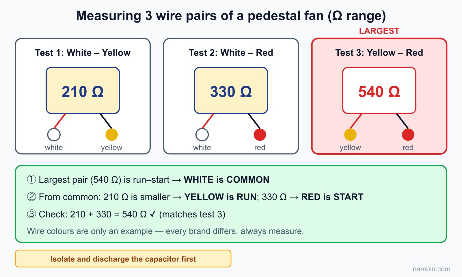
A customer brings in a three-wire pedestal fan; another repairer removed the capacitor and nobody remembers how it was connected. You measure: white–yellow 210 Ω, white–red 330 Ω, yellow–red 540 Ω (see Figure 2).
- The largest reading is 540 Ω on the yellow–red pair, so that is run–start and white is the common wire.
- From white: to yellow 210 Ω (smaller), so yellow is run; to red 330 Ω (larger), so red is start.
- Check: 210 + 330 = 540 Ω, exactly the yellow–red reading.
Pump windings have much lower resistance (a few ohms), so remember to subtract the probe resistance. There is a worked example in the pump section below.
| Result | Meaning | Action |
|---|---|---|
| Three sensible readings, the two smaller ones add up to roughly the largest | Windings are healthy | Identify the wires and wire the capacitor |
| One pair shows "OL" (infinite) | Open winding or blown thermal fuse inside the motor | Check the thermal fuse (fans), rewind or replace the motor |
| One pair close to 0 Ω | Shorted turns or two leads touching | Do not power it up; rewind or replace |
| Any lead to the frame below about 1 MΩ (measured with a 500V insulation tester) | Poor insulation, risk of leakage and shock | Dry it out and re-test; if still low, rewind |
Fan capacitor wiring diagrams: pedestal, desk and three-wire ceiling fans
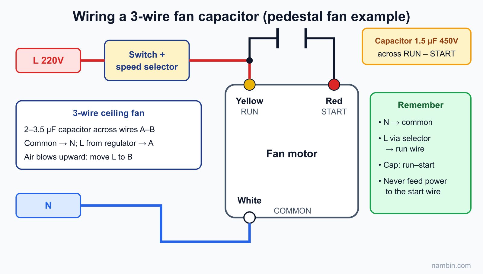
Once you know common, run and start, the diagram comes down to one rule: supply to common and run, capacitor between run and start. The only difference between fan types is the speed selector that sits in the supply line.
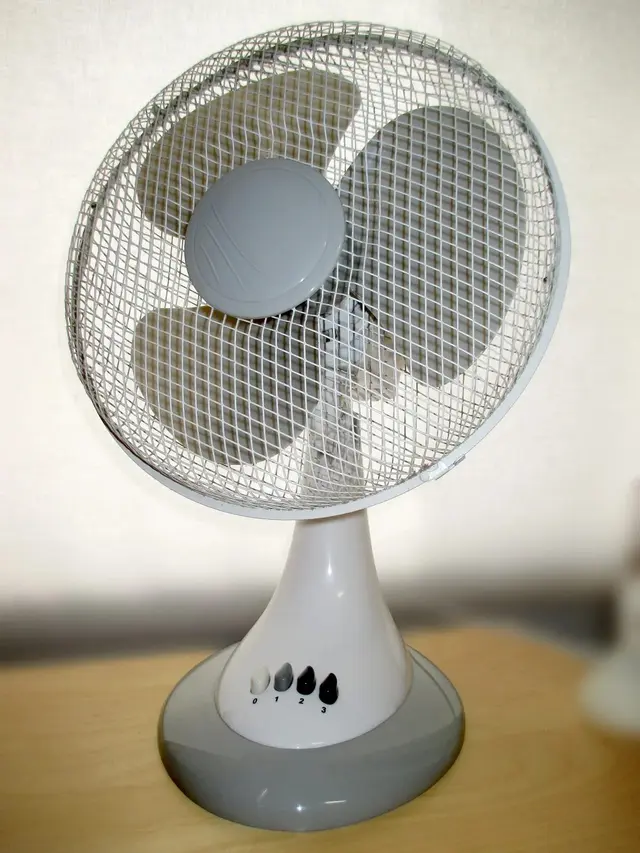
Pedestal and desk fans with speed buttons
Pedestal fans often have more than three wires because the run winding has extra taps for speeds 1, 2 and 3. The common wire still goes straight to one side of the supply (often through a thermal fuse). The other side of the supply goes through the speed buttons to the taps on the run winding. The capacitor still sits between the end of the run winding and the start wire. For a fan with just three wires and a separate speed selector, wire it as in Figure 3.
How to wire a three-wire ceiling fan
A ceiling fan has three leads from the motor, and sometimes the capacitor is already fitted inside the canopy. Wire it like this:
- Measure to find the common wire from the largest pair. Ceiling fans usually have two windings of almost equal size (for example common–A 125 Ω, common–B 130 Ω, A–B 255 Ω), so just call the other two wires A and B.
- Connect the ceiling fan capacitor (usually 2–3.5 µF, check the old one) between A and B.
- Connect the common wire to the neutral N at the ceiling.
- Connect the live L from the speed regulator (the knob on the wall) to A.
- Switch on at low speed and stand under the fan: in summer the air must blow downwards. If it blows upwards, switch off and move L from A to B (the capacitor stays between A and B).
Hanging the fan, the hook and anti-vibration are covered in the Vietnamese lesson Installing a ceiling fan correctly.
Reversing a fan — and why you cannot do it with a pump
The direction of rotation depends on which winding receives current through the capacitor. On a ceiling fan with two nearly equal windings, swapping the roles of A and B reverses it. On pedestal fans and pumps the start winding is much smaller than the run winding; if you feed power straight into the start winding it overheats and burns out within minutes. A pump has a fixed direction set by its impeller; if a pump runs backwards, re-check the wiring instead of "swapping to see what happens".
How to wire a single-phase water pump capacitor
Booster pumps, well pumps and household pressure pumps on single phase are all capacitor motors. The terminal box on the pump body usually has a terminal block marked C, R (or M) and S (or A), with the capacitor mounted on the box lid. If the markings are gone or the pump has been rewound, measure it the same way as a fan.
Worked example: a 0.75 kW (1 HP) booster pump
In a four-storey townhouse, a 0.75 kW, 220V booster pump hums and then trips the breaker. The old capacitor has a bulging top and reads 20 µF 450V. After isolating the power and discharging the capacitor, you remove the three wires from the terminal block; the probe resistance is 0.2 Ω. Readings with the probe resistance subtracted: wires 1–2 = 3.4 Ω, 1–3 = 9.6 Ω, 2–3 = 13.0 Ω.
- The largest is 13.0 Ω (2–3), so wire 1 is common.
- 1–2 = 3.4 Ω (smaller), so wire 2 is run; 1–3 = 9.6 Ω, so wire 3 is start.
- Check: 3.4 + 9.6 = 13.0 Ω — it matches (see Figure 4).
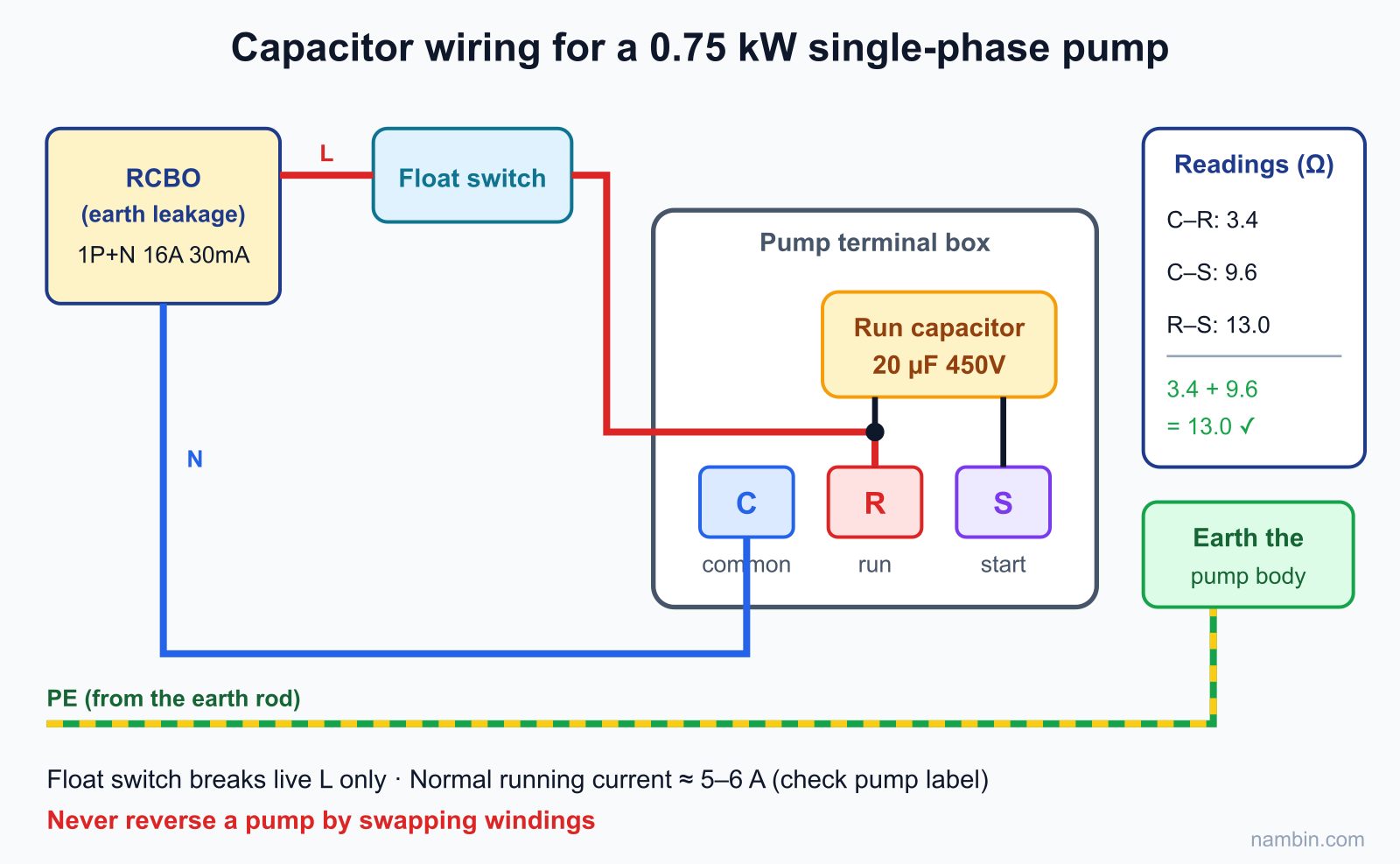
Wiring it to the diagram
- Connect the neutral N to terminal C (common).
- Connect the live L — after the RCBO and after the float switch — to terminal R (run). The float switch only breaks the live, never the neutral.
- Connect the two legs of the 20 µF 450V capacitor to R and S. A run capacitor has no polarity, so either leg can go to either terminal.
- Connect the earth wire (green/yellow) to the earth screw on the pump body.
- Tighten the terminals and close the box lid with its waterproof gasket. Prime the pump with water before switching on; never run it dry.
- Switch on and measure the current with a clamp meter: a 0.75 kW pump normally draws about 5–6 A (compare with the rating plate). A current clearly above the plate value plus heat means a fault remains.
If the pump runs smoothly with the correct current but still delivers no water, it is not an electrical fault — see the Vietnamese lesson Pump runs but delivers no water to check priming, the foot valve and the suction pipe.
Pumps with an extra start capacitor and a centrifugal switch
Pumps from about 1.1 kW upwards, deep-well pumps and older pumps may have two capacitors: a run capacitor (metal or white plastic case, tens of µF) and a start capacitor (black case, 100–300 µF). The start capacitor is in series with a centrifugal switch inside the motor or with a start relay; when the motor reaches about 70–80% of its speed, the switch cuts the start capacitor out. With this type, photograph the terminal box before removing anything, put each capacitor back in its own place, and never replace a start capacitor with a run capacitor or vice versa.
Failed fan capacitor: symptoms and how to test it
The capacitor is the part that fails most often in fans and pumps, because it heats up year after year, dries out and loses capacitance. Testing the capacitor before suspecting the bearings or the windings saves a lot of time.
Symptoms
- The fan turns much slower than before; speed 3 feels like speed 1.
- The fan hums when switched on and does not turn by itself; give it a push and it turns in the direction you pushed.
- The pump hums, heats up quickly, and the thermal overload or the breaker trips after a few seconds.
- The capacitor has a bulging top, a cracked case, leaks oil or smells burnt.
Note: a fan that is stiff to turn by hand (tight shaft, dry bushings) also runs slowly. With the power off, spin the blades by hand: they should turn freely and coast for a few more turns. The Vietnamese lesson Fan not turning, turning weakly or humming has a full diagnostic tree for bushings, windings and the thermal fuse.
Measuring capacitance with a meter that has a µF range
- Remove the capacitor from the circuit and discharge it.
- Set the meter to the capacitance range (marked with a capacitor symbol or "F") and measure across the two legs.
- Compare with the value printed on the case. Capacitors are marked with a ±5% tolerance: a 1.5 µF capacitor reading 1.43–1.58 µF is still good. About 10% below the marked value, replace it; a 1.5 µF capacitor reading only 1.1 µF definitely has to go.
- If the meter shows "OL" or close to 0 µF, the capacitor is open or shorted: replace it straight away.
Choosing a replacement: microfarads, voltage and capacitor type
Rule number one: replace with the same µF as the old capacitor or the motor plate. If the print on the old one has faded, check the motor plate, the manual or the reference table below, then confirm with the running current.
| Appliance | Typical run capacitor | Recommended capacitor voltage |
|---|---|---|
| Desk, pedestal and wall fans | 1–2 µF (often 1.2, 1.5 or 1.8 µF) | 400–450 VAC |
| Extractor and small ventilation fans | 1–2 µF | 400–450 VAC |
| Ceiling fans | 2–3.5 µF (often 2.5 µF) | 400–450 VAC |
| Pumps 125–250 W | 6–10 µF | 450 VAC |
| Pumps 370 W (0.5 HP) | 12–16 µF | 450 VAC |
| Pumps 750 W (1 HP) | 16–25 µF (example in this lesson: 20 µF) | 450 VAC |
What happens if the µF is wrong?
- Too small: weak starting torque, the fan turns slowly, the pump struggles to start and hums.
- Too large: at first it seems "stronger", but the current in the start winding rises, the motor runs hot and the start winding soon burns out. Never "upsize the capacitor to make the fan stronger".
Voltage rating and capacitor type
The voltage printed on the new capacitor must be equal to or higher than the old one: a 250V capacitor can be replaced by a 400V or 450V one; a 450V capacitor must never be replaced by a 250V one. The reason: in a motor circuit the voltage across the capacitor is usually higher than 220V because it resonates with the winding. Choose an AC film or oil-filled capacitor (CBB61 for fans, CBB60/CBB65 for pumps) clearly marked "µF ±5%" and "VAC". A start capacitor must be replaced by a start capacitor in the same µF range.
Scenario: the fan capacitor only says "1.5"
In the pedestal fan example, the old capacitor measures only 1.1 µF and the case says "1.5 µF 250V". You replace it with a 1.5 µF 450V capacitor (a higher voltage rating is safer) and wire it as in Figure 3. All three speeds work and the motor case is just warm after 30 minutes: job done.
Safety when replacing a capacitor: isolate, discharge, re-check
A capacitor holds its charge after the plug is pulled. A small fan capacitor usually gives only a mild jolt, but a pump capacitor of several tens of µF can give a strong shock that makes you jerk your hand into a sharp edge or fall off a ladder.
Safety warning: Always switch off the breaker (not just the wall switch), hang a "Work in progress" tag, and use a tester pen or a meter to prove that both L and N are dead. Then discharge the capacitor with a resistor of about 10–20 kΩ, 2–5 W clipped between two insulated probes, hold it for a few seconds, and measure the voltage across the capacitor legs on the VDC/VAC range: it must be close to 0V. Never short the legs with a screwdriver — the spark burns the terminals, pits the screwdriver tip and throws hot metal. Never measure winding resistance while the motor is live. A pump in a damp location must have a 30 mA RCBO and an earthed body; never work with your feet in water.
The energy in a capacitor is W = ½·C·U². A 20 µF pump capacitor can still hold up to the peak voltage of about 311V (220V × 1.41): W ≈ 0.5 × 0.000020 × 311² ≈ 0.97 J — enough for a hard shock and a visible spark.
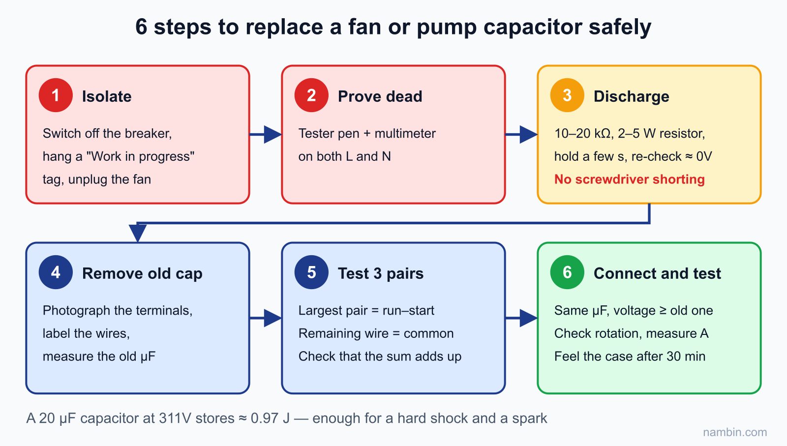
The six-step procedure (see Figure 5)
- Switch off the breaker, hang a tag, unplug (for fans).
- Prove dead with a tester pen and a multimeter.
- Discharge the capacitor through a resistor and re-check that its voltage is about 0V.
- Photograph the terminal box, label the wires, remove the old capacitor and measure its µF.
- Measure the resistance of the three wire pairs, identify common, run and start, and check the sum.
- Fit a new capacitor with the right µF and voltage; switch on, check the direction, measure the current and feel the temperature after 30 minutes.
Common capacitor wiring mistakes and how to fix them
Supply connected to the start wire
Symptom: the fan turns very weakly or backwards, the motor heats up fast and smells burnt. Cause: run and start were mixed up by guessing from the colours. Fix: switch off at once, measure the three pairs again and move the supply back to common and run. Test the insulation of the start winding before using it again.
Fitting a bigger capacitor "for more power"
Symptom: runs strongly right after the replacement, then the winding burns out a few weeks later. Cause: the start winding current exceeds its design. Fix: go back to the correct µF; if the fan is still weak with the correct capacitor, check the bushings, the blades and the supply voltage.
Frequently asked questions
How do I wire a three-wire fan capacitor correctly?
Measure the resistance of the three wire pairs to find common, run and start. Connect the supply to common and run (usually N to common, L through the speed selector to run), and connect the capacitor between run and start. Check the air direction before refitting the blades and the guard.
How do I wire a three-wire ceiling fan when I do not know the colours?
You do not need the colours. The pair with the highest resistance is the two ends that take the capacitor; the remaining wire is common and goes to N. The live from the speed regulator goes to one of the two capacitor wires; if the fan turns the wrong way, move it to the other one.
Is a pump capacitor wired differently from a fan capacitor?
The principle is identical: supply to C and R, capacitor across R and S. The differences are that the capacitor is much larger (about 16–25 µF for a 0.75 kW pump), you need an RCBO, an earthed body and a waterproof terminal box, and you must never reverse a pump by swapping windings.
What are the signs of a failed fan capacitor?
The fan hums but does not start by itself and only turns when pushed; it turns slowly even on the highest speed; the capacitor is bulging or leaking oil. Measure it on the µF range: about 10% or more below the marked value means replace it.
Can I replace a 250V capacitor with a 450V one?
Yes, and it will last longer, as long as the µF value is the same. The other way round — replacing a 450V capacitor with a 250V one — is not allowed.
Practice exercises and self-assessment
Exercises
- A fan has three wires: blue, black and brown. Readings: blue–black 280 Ω, black–brown 190 Ω, blue–brown 470 Ω. Identify common, run and start, and draw the wiring diagram for a 1.5 µF capacitor.
- A 370 W pump gives (probe resistance already subtracted): 1–2 = 11.2 Ω, 1–3 = 4.8 Ω, 2–3 = 16.0 Ω. Identify C, R and S and choose a run capacitor from the table.
- On a training bench, under the supervision of a master electrician: isolate the power, discharge, and measure the µF of an old fan capacitor; write down your verdict, "still usable" or "replace".
- Calculate the energy stored in a 16 µF capacitor at 311V.
Self-assessment criteria
- Exercise 1 is a pass if you get: black is common (not part of the largest pair, 470 Ω), brown is run (190 Ω), blue is start (280 Ω); check 190 + 280 = 470 Ω. Diagram: supply to black and brown, capacitor between brown and blue.
- Exercise 2 is a pass if you get: wire 1 is C, wire 3 is R (4.8 Ω), wire 2 is S (11.2 Ω); 4.8 + 11.2 = 16.0 Ω; a 12–16 µF 450V capacitor (the value on the old one comes first).
- Exercise 3 is a pass if you follow the full order isolate – prove dead – discharge – measure; skipping the prove-dead or discharge step is a fail.
- Exercise 4 is a pass if you get W = 0.5 × 0.000016 × 311² ≈ 0.77 J.
Keep learning with a mentor: to have your winding tests, capacitor wiring, float switch and contactor work for pumps and three-phase motors graded like a master electrician, join the Residential Electrician Level 3 – Master Electrician course. See every step in the Residential Electrician roadmap.
Next step in the roadmap (Heavy loads & surge protection): once you have mastered single-phase motors and pumps, you will learn to run dedicated circuits for air conditioners, induction hobs, water heaters and EV chargers, and to fit surge protective devices (SPD) for the whole house.