The distribution board is the "heart" of a home's electrical system. However neatly the cables are run, if the board is wired carelessly, fitted with the wrong protective devices or has no earthing, people can still get a shock when they touch the washing machine. This lesson explains what MCBs, RCCBs and RCBOs actually do, how to lay out a board for a house, how to wire the busbars neatly, and how to build and measure an earthing system with real numbers for the handover.
It follows on from the step on installing lighting circuits, switches and sockets: the cable runs you have already installed now come back to the board, get their protective devices and are connected to the earthing system.
By the end of this lesson, you will be able to:
- Draw up an equipment list and choose an enclosure size for a typical Vietnamese townhouse ("nha pho").
- Route the neutral correctly through each RCBO so devices do not trip for no reason.
- Build an earth rod system and measure it with the three-pole (fall-of-potential) method.
- Prepare a test record to hand over to the homeowner.
Which device protects against what
Each protective device covers a different hazard. Choosing the wrong one means missing protection — not "good enough for now".
| Device | Protects against | Where it is used |
|---|---|---|
| MCB (miniature circuit breaker) | Overload and short circuit — protects the cable | Main switch and every final circuit |
| RCCB (residual current circuit breaker) | Leakage current to earth — protects people; does not protect against overload | Upstream of a group of circuits, always together with MCBs |
| RCBO | Overload, short circuit and leakage in a single device | Socket circuits, bathrooms, water heaters, washing machines, outdoor circuits |
| ELCB | An older name often used for leakage protection devices | Read the label carefully to find out whether it is really an RCCB or an RCBO |
For protecting people, common practice is to use residual current devices with a 30 mA rating on socket circuits and in wet areas. If one leakage device covers the whole house, a single damp socket can black out everything. So it is better to split RCBOs by circuit group, or to use a higher-rated, time-delayed (type S) main RCD coordinated with 30 mA RCBOs on the branches, as the design specifies.
Reading the ratings printed on the device
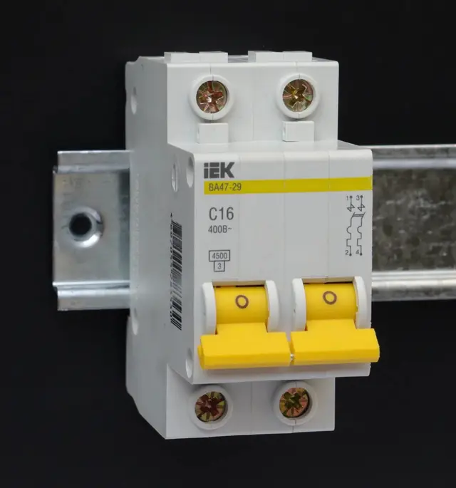
- Rated current and tripping curve (for example C16): the letter is the instantaneous tripping curve, the number is the rated current in amperes. Homes normally use curve C.
- Short-circuit breaking capacity (for example 4500 or 6000, in A): the largest short-circuit current the device can safely interrupt. Choose it according to the design; houses close to a transformer substation see higher fault currents.
- Number of poles: 1P switches one conductor, 1P+N switches phase and neutral in one module, 2P switches both conductors. The main breaker should switch both phase and neutral so the installation is fully isolated during repairs.
- Residual current rating (IΔn) on RCCBs/RCBOs: 30 mA for personal protection; 100 mA or 300 mA are typically used for fire protection or as a time-delayed upstream stage.
- Type AC or type A: type AC detects alternating leakage current; type A also detects pulsating DC leakage — manufacturers often recommend it for washing machines, inverter-driven appliances and induction hobs. Check the appliance installation instructions before choosing.
Why 30 mA, and why homes really need leakage protection
A current of a few tens of milliamps through the body can already cause muscle contractions you cannot let go of, and heart rhythm disturbances if it lasts. A 30 mA threshold combined with a very short tripping time greatly reduces that risk. In many Vietnamese residential areas the neutral is earthed at the transformer, while the metal casings inside the house are connected to the house's own earth rod (a TT arrangement). The fault current from a casing then has to travel through the soil from the house rod back to the substation. That path has enough resistance that the fault current may not trip the MCB quickly, while the casing still carries a dangerous voltage.
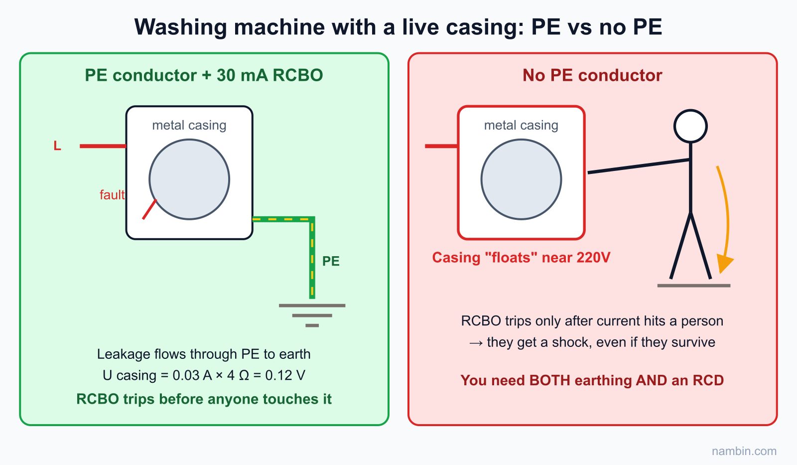
The residual current device fixes exactly this weak point: a leakage of a few tens of milliamps is enough to trip it. Earthing and leakage protection are two complementary layers; neither replaces the other. The section "Building and measuring the earthing system" below works this out with numbers (see Figure 1).
Laying out a sample townhouse board
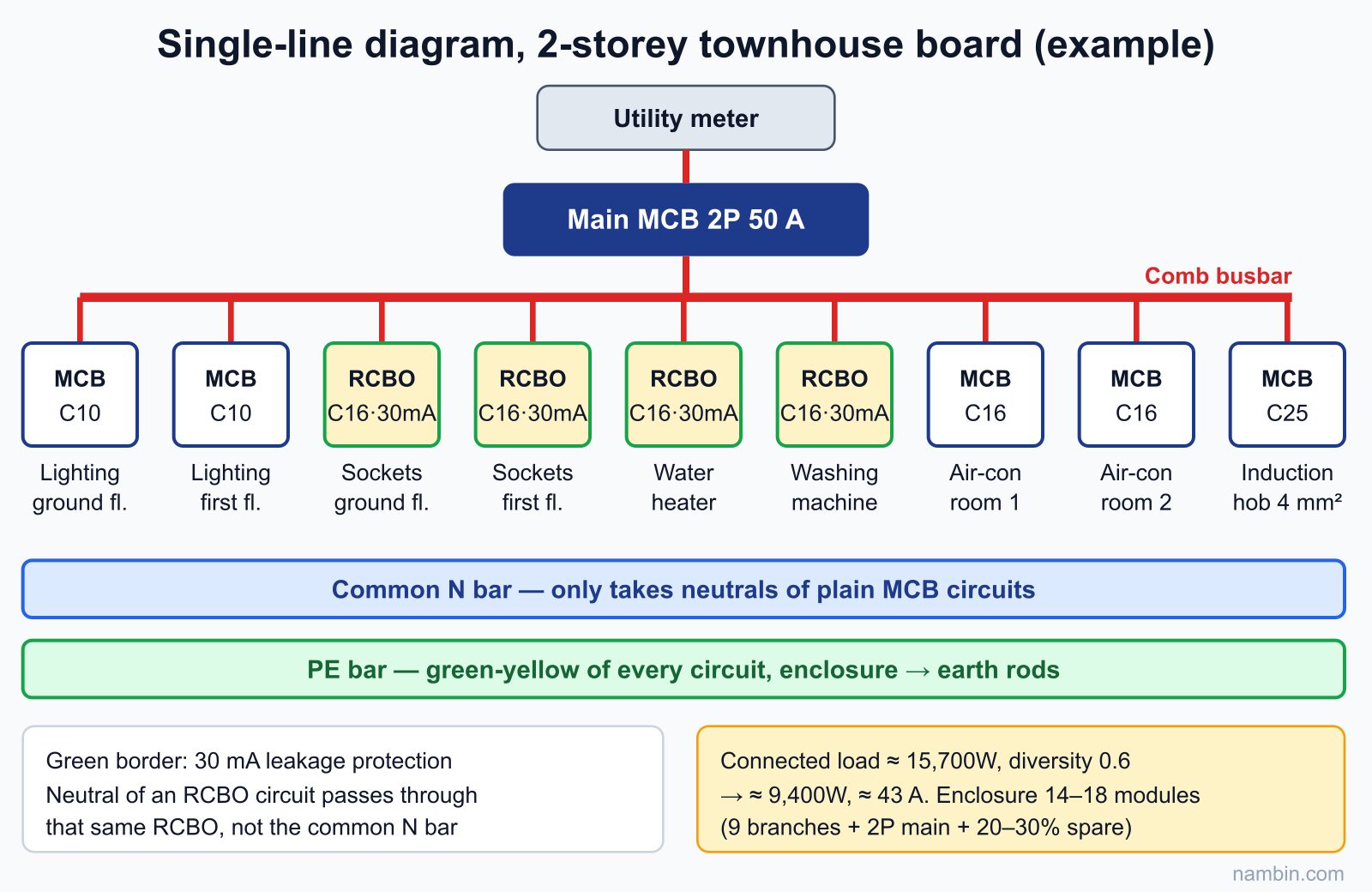
Example: a board for a two-storey house, single-phase 220V/50Hz supply, located after the utility's electricity meter:
- Two-pole main MCB switching both phase and neutral, rated according to the load calculation from the previous step.
- Lighting row: one 1P+N MCB per floor.
- Socket row: one 30 mA RCBO for the sockets on each floor.
- Dedicated circuits: RCBOs for the water heater and washing machine; MCBs for air conditioners and the induction hob according to their power (check the appliance catalogues).
- Neutral bar (N) and earth bar (PE) kept separate, with enough terminals for every circuit plus a few spares.
- Leave 20–30% of the DIN rail free for circuits added later.
Stick the single-line diagram and a circuit chart on the inside of the board door. The user must be able to tell immediately which breaker feeds which room.
Worked example: equipment list for the board
A two-storey townhouse with two rooms per floor, a double induction hob, a water heater, a washing machine and two air conditioners. Applying I = P/U and the rule "the breaker protects the cable" from the load calculation step gives this reference list:
| Circuit | Estimated power | Current (I = P/220) | Cable | Protective device |
|---|---|---|---|---|
| Lighting, ground floor | 400W | ≈ 1.8 A | 1.5 mm² | MCB 1P+N C10 |
| Lighting, first floor | 400W | ≈ 1.8 A | 1.5 mm² | MCB 1P+N C10 |
| Sockets, ground floor | 2000W | ≈ 9.1 A | 2.5 mm² | RCBO C16, 30 mA |
| Sockets, first floor | 2000W | ≈ 9.1 A | 2.5 mm² | RCBO C16, 30 mA |
| Water heater | 2500W | ≈ 11.4 A | 2.5 mm² | RCBO C16, 30 mA |
| Washing machine | 2000W | ≈ 9.1 A | 2.5 mm² | RCBO C16, 30 mA |
| Air conditioner, room 1 and room 2 (each circuit) | 1200W | ≈ 5.5 A | 2.5 mm² | MCB C16 |
| Double induction hob | 4000W | ≈ 18.2 A | 4 mm² | MCB C25 (per hob catalogue) |
Total connected load: 400 + 400 + 2000 + 2000 + 2500 + 2000 + 2 × 1200 + 4000 = 15,700W. Not everything runs at once; with an estimated diversity factor of about 0.6, the design load is about 9,400W and the current about 9,400/220 ≈ 43 A. A 2P main MCB of about 50 A would fit, but it must match the cable size after the meter and the capacity registered with the utility. These figures only illustrate the method; on a real job, follow the drawings and equipment catalogues.
Counting modules: one 2P main (2 modules) + 9 branches; add 20–30% spare, so choose an enclosure of about 14–18 modules (some RCBOs take 2 modules — count from the actual catalogue). Figure 2 shows the resulting single-line diagram.
Coordinating the main breaker and the branches
When a fault occurs on one branch, only that branch breaker should trip; the other rooms keep power. For that, the main breaker rating must be clearly higher than the largest branch. If leakage protection is used at both levels, the upstream device must have a higher threshold and a time delay (type S). Two 30 mA devices without delay in series may both trip on a leak, and the whole house goes dark.
Installing and wiring the board step by step
Tools: insulated screwdrivers, a torque screwdriver or torque wrench (if the manufacturer specifies tightening torque), wire strippers, a ferrule crimping tool, pin ferrules, cable markers, a multimeter, an insulation resistance tester (megger) and an earth resistance tester.
- Mount the enclosure: in a dry, easily accessible place, never in the bathroom or right next to the cooker; at a comfortable working height, out of reach of small children.
- Fit the devices on the DIN rail in this order: main switch → leakage devices → branches. Keep devices with the same function next to each other.
- Run the cables inside the board: use trunking or tidy bundles, bend at right angles, never cross in front of the breakers. Phase, neutral and earth must be the correct colours.
- Crimp pin ferrules onto flexible stranded conductors before clamping them into breaker terminals; tighten to the correct torque and give each wire a pull test.
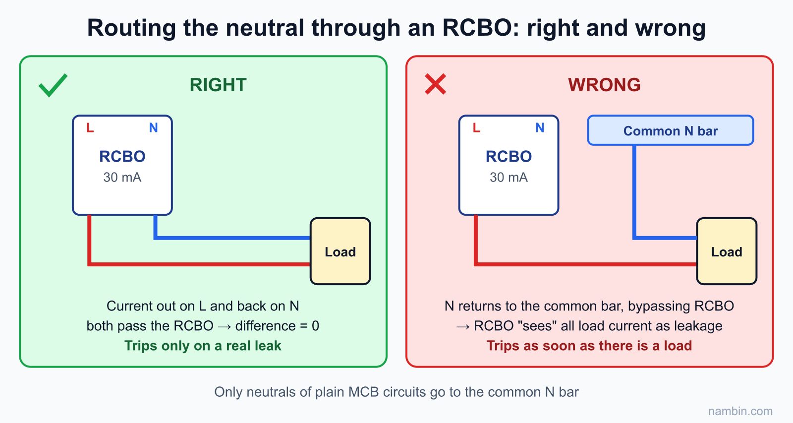
- Connect each neutral to the right branch: the neutral of a circuit protected by an RCBO/RCCB must pass through that same device, not go to the common N bar. Getting this wrong makes the leakage device trip constantly.
- Connect the earthing: every PE conductor from the branches goes to the PE bar, and the PE bar connects to the earthing conductor running down to the rods.
- Label everything and take photos of the board before fitting the cover.
Safety: The supply side of the main MCB is always live from the grid. Connecting to the meter and the line before the meter is the utility's job — never do it yourself. Only work inside the board after switching off the supply, applying lock-out/tag-out and testing for dead at both the incoming and outgoing terminals.
Routing the neutral through an RCBO: a concrete example
The ground-floor socket circuit leaves the board with a red phase conductor and a blue neutral. The red wire goes to the L outgoing terminal of the RCBO, and the blue wire goes to the N outgoing terminal of that same RCBO. The RCBO's incoming side takes phase from the main breaker (via a busbar or comb bar) and neutral from the N bar.
If the blue wire of this circuit accidentally goes to the common N bar, current leaves through the RCBO but returns without passing through it. The device "sees" the whole load current as leakage and trips as soon as a load is connected (see Figure 3). Only the neutrals of plain MCB circuits go to the common N bar.
A tidy wiring order inside the board
Connect the incoming supply first, then the comb bar feeding phase to the branches, then the outgoing cables of each circuit from left to right in the same order as the circuit chart. Earth conductors run along the edge of the enclosure to the PE bar. Each busbar terminal should take only one conductor unless the manufacturer allows more. Leave enough slack so that a breaker can be removed and replaced later without stretching the cables.
Building and measuring the earthing system
Earthing lets leakage current flow into the ground, with enough current for the leakage device to trip quickly instead of the current flowing through a person. A common approach for houses:
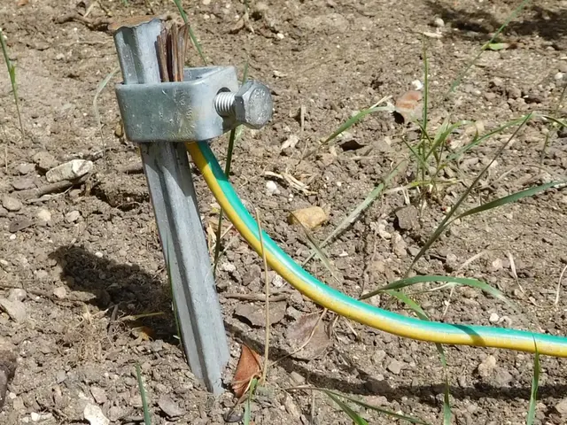
- Earth rods: usually copper-bonded steel rods about 2.4 m long, driven vertically. Multiple rods are spaced at least one rod length apart, with the rod tops about 0.5–0.8 m below ground.
- Bonding: join the rods with bare copper cable or copper tape, using exothermic welding or purpose-made corrosion-resistant clamps.
- Earthing conductor: green-yellow insulated copper cable from the inspection pit up to the PE bar in the board, sized according to the design.
- Inspection pit: with a cover, for later re-testing and maintenance.
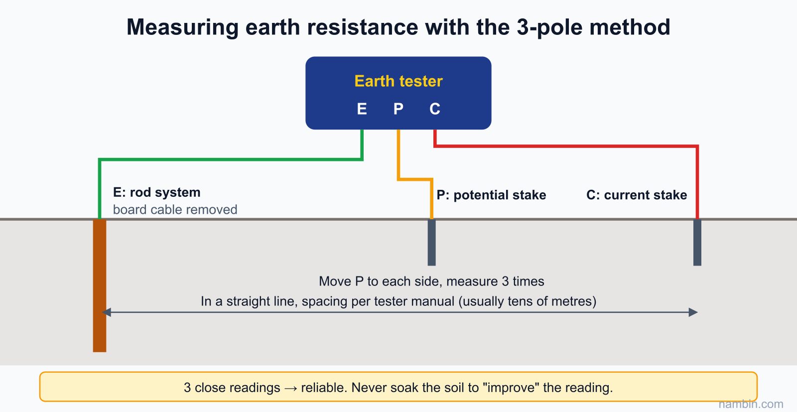
- Measure the earth resistance: use an earth resistance tester with two auxiliary stakes (the three-pole method). Many residential design documents in Vietnam require a protective earth resistance of no more than 4 Ω — refer to TCVN 9358 (the Vietnamese national standard for earthing in industrial and residential buildings) and the project drawings. If it does not pass, drive more rods or treat the soil to lower its resistance according to technical guidance.
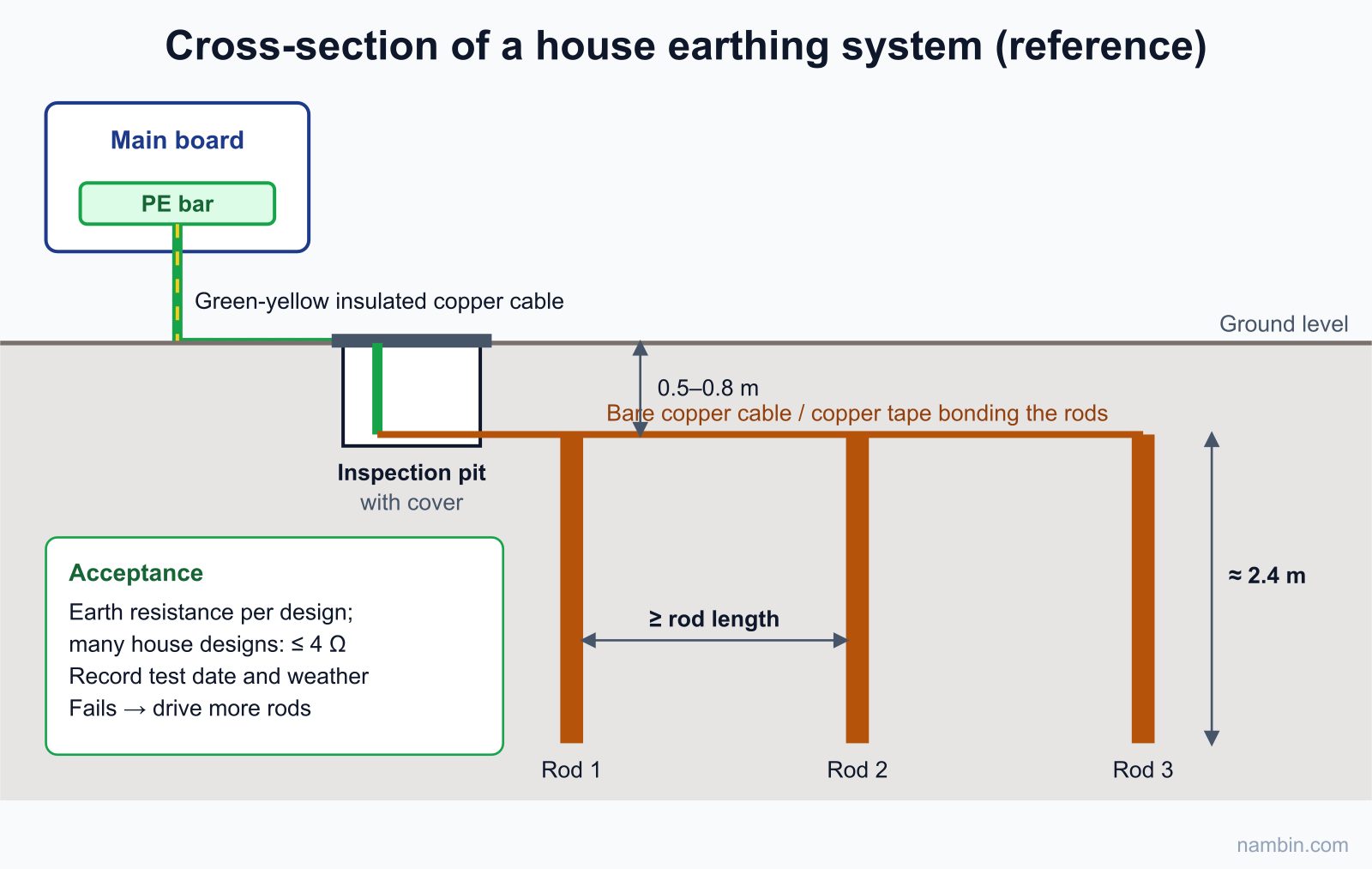
Record the result, the date and the weather (dry soil gives higher readings than damp soil) in the acceptance record.
Worked example: what good earthing does when a casing becomes live
Suppose the phase conductor inside a washing machine touches its metal casing. The casing voltage relative to earth is roughly the current flowing to earth times the earth resistance: U = I × R. A common check under IEC 60364 for this earthing arrangement: earth resistance times the RCD tripping threshold must not exceed the permissible touch voltage, usually taken as 50 V.
With a 30 mA RCBO and a 4 Ω earth: 0.03 × 4 = 0.12 V. Even 100 Ω gives only about 3 V — far below 50 V. In other words, by the time the leakage is just enough to trip the RCBO, the casing still has no dangerous voltage. Real fault currents are usually many times the threshold, so the RCBO trips almost instantly.
Without a PE conductor, the casing "floats" at nearly 220V. The current has no path to earth, so the RCBO does not trip. Only when someone touches it does current flow through the person to earth and the RCBO detects it. The device may still save that person's life, but they have already received a shock. That is why you need both layers: earthing and leakage protection.
Measuring earth resistance correctly
With the board switched off, disconnect the earthing conductor from the rods in the inspection pit so you measure the rod system alone. Drive the two auxiliary stakes in a straight line away from the main rods, at the distances given in the tester's instructions — usually a few tens of metres. After measuring, move the potential stake a little to each side and measure again; if the three readings are close, the result is reliable (see Figure 5).
Reconnect the earthing conductor, tighten it, and only then switch the power back on. Never measure right after soaking the ground with water to "improve" the figures.
When the earth resistance does not pass
Drive additional rods, keeping the spacing at least equal to the rod length so they do not "shadow" each other, bond them with bare copper and measure again. On rocky ground or dry sand you may need soil treatment designed by an engineer — note it clearly in the record instead of reaching the number with tricks.
Common mistakes
- Joining N and PE in a sub-board: this defeats the leakage device and can put voltage on appliance casings.
- Using a water pipe as the earth: plastic pipes do not conduct, and metal pipes can be replaced with plastic at any time.
- Fitting a bigger breaker "so it stops tripping": the cable will overheat before the breaker trips.
- Not crimping ferrules on flexible cable: the copper strands splay out, make poor contact and heat up.
- Never pressing the TEST button: a leakage device can fail without anyone noticing. Show the homeowner how to test it regularly as the manufacturer recommends.
- Too many circuits behind one leakage device: symptom — nuisance tripping, especially when many electronic appliances are on. Cause — the small leakage currents of each appliance add up. Fix — split RCBOs by circuit as in the example table.
- Metal enclosure not connected to PE: symptom — the voltage tester lights up when touching the enclosure. Fix — bond the enclosure and its door to the PE bar with flexible green-yellow cable.
Frequently asked questions
Do lighting circuits need an RCBO?
Lighting in dry rooms usually only needs an MCB, as in the example above. Lights in bathrooms, outdoors, on roof terraces, or fittings with easily reachable metal bodies should have leakage protection; follow the design drawings.
Is one main RCCB for the whole house enough?
It is enough to provide leakage protection, but every time one socket gets damp the whole house loses power, and the faulty circuit is hard to find. Splitting RCBOs by circuit costs more at first but is much easier to live with and to repair.
What if the RCBO does not trip when I press TEST?
Switch off that circuit and check that the device's supply is connected correctly. If it is wired correctly and still does not trip, the device is faulty — replace it with one of the same rating and stop using the old one.
The house is already built and there is nowhere to drive rods. What now?
Look for a spot in the yard, a drainage pit or a strip of soil beside the house; you may be able to drill through the ground-floor slab if the structure allows and the homeowner agrees. In complicated cases, recommend a survey by an engineer rather than skipping the earthing.
Can the N and PE bars in the board be connected together?
In a normal residential board, no. Joining them is only done at the point defined by the system design; if you are not sure, keep them separate and ask the designer.
Acceptance checklist and exercises
- Every circuit has the right type of protective device, rated to match the cable size.
- Socket circuits and wet areas have 30 mA leakage protection; the TEST buttons work.
- N and PE bars are separate; each neutral passes through its own circuit's leakage device.
- Earth resistance meets the design requirement, with a recorded reading and photos.
- The board has a diagram, circuit labels and spare space.
- Practical exercise: on a training board, install a main MCB, 2 lighting MCBs, 2 socket RCBOs and N/PE bars; connect them to the circuit board from the switches and sockets lesson. Record the insulation resistance of each circuit and test every RCBO with its TEST button.
- Paper exercise: draw up the equipment list for the board of the house you live in, following the example table, with columns for power, current, cable, protective device and the number of enclosure modules.
Self-assessment criteria (pass / not yet):
- Every task inside the board was done after switching off, lock-out/tag-out and testing for dead on both incoming and outgoing sides.
- Each RCBO trips when TEST is pressed, and does not trip randomly with a real load plugged in (proof that the neutral is wired correctly).
- Ferruled conductors are firm and do not pull out; no cables cross in front of the breakers.
- The circuit chart matches reality: switching off each breaker cuts power to exactly that room.
- The record includes insulation resistance for each circuit, earth resistance, the test date and the weather.
- You can explain why both earthing and leakage protection are needed and why neither replaces the other.
Once you can install final circuits and a distribution board, you have the foundation for the next step: troubleshooting common electrical faults — tracing tripping breakers, leakage and hot sockets on a system whose construction you understand thoroughly.