A stairwell light that cannot be switched on downstairs and off upstairs, a washing-machine socket without an earth wire, a taped joint that melts after a few months — most of these come from mistakes made during the original installation. This lesson shows you how to install a lighting circuit with one-way and two-way switches plus earthed sockets, from running cable in conduit to testing before you switch the power on. By the end of this lesson, you will be able to: wire one-way, two-way and intermediate switches correctly (controlling a light from 3 positions); install 3-pin sockets with a real earth wire; calculate conduit fill yourself; and produce a table of continuity and insulation readings that proves the circuit meets requirements at handover.
This lesson follows the step "Reading diagrams and calculating loads": you already know how to divide circuits and choose cable sizes, and now it is time to turn the drawing into real cable inside the wall. Every task in this lesson is carried out on a circuit that is switched off; switching on is only the last step, after all tests have passed.
Core principles before you pick up a cable
If you understand why, you will not need to memorize each diagram mechanically.
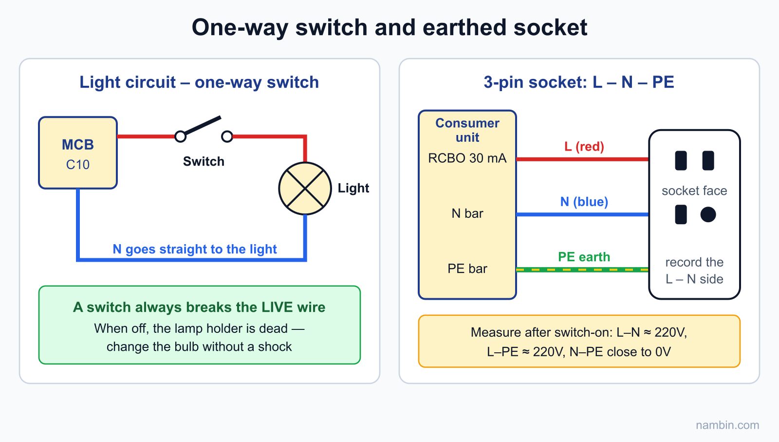
- A switch always breaks the live (phase) wire, never the neutral. If the switch breaks the neutral, the lamp holder is still live relative to earth when the light is off — whoever changes the bulb can get a shock even though "the light is off".
- Know the wire colors and keep them consistent throughout the house. Under the common convention (IEC, with equivalent Vietnamese TCVN standards): live is brown or red, neutral is blue, earth is green-and-yellow. The strapper (traveler) wires of a two-way switch should use a clearly different color (for example black or grey) so the next electrician can recognize them.
- Joints sit in a junction box, never in the middle of a conduit. A junction box must be openable for inspection. A joint stuck inside a conduit is a place where heat builds up, and nobody can find it when something goes wrong.
- An earthed socket must have a real earth wire. Fitting a 3-pin socket without connecting the green-and-yellow wire only gives the user a false sense of safety.
In this lesson's figures, live wires are drawn red, neutral blue, earth green with yellow stripes, and strapper wires black/grey.
Why the joint is the weakest point of a circuit
Copper cable of the right size hardly heats up at its rated load. The hot spot is where two metal surfaces touch: if the contact is poor, the resistance there rises, and the heat produced follows P = I²R. For example, a joint with a contact resistance of only 0.1 Ω, on a socket circuit carrying 10 A, gives off about 10² × 0.1 = 10 W — like a small light bulb glowing continuously inside a closed box. The heat oxidizes the copper, the resistance rises further and the joint gets even hotter: a vicious circle that ends with the cable insulation burning. That is why good electricians spend more time on joints than on pulling cable.
Why cable must run in conduit
Conduit protects the insulation from knocks, cement mortar and rats; more importantly, it lets you pull the cable out and replace it later without breaking the wall. Cable buried directly in plastered walls is the kind of work that forces the owner to break open a whole wall when one section of cable fails.
One-way switch, two-way switch and socket diagrams
One-way switch
The live wire from the circuit breaker goes to one terminal of the switch, and the other terminal goes to the light. The neutral wire runs directly from the neutral bar to the light. This is the most basic circuit, used for bedrooms and toilets.
Two-way switch (stairs, corridors)
Each two-way switch has 3 terminals: one common terminal (usually marked C, COM or L) and two strapper terminals (L1, L2). How to wire it:
- The live wire goes to the common terminal of the first switch.
- Two strapper wires connect L1 – L1 and L2 – L2 between the two switches.
- The common terminal of the second switch goes to the light.
- The neutral runs straight to the light, without passing through any switch.
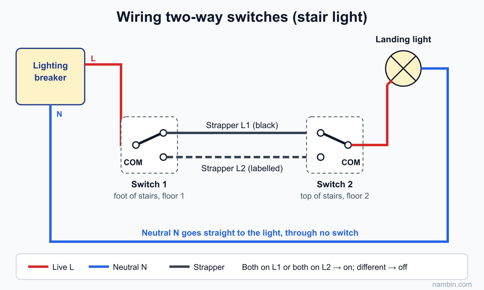
The most common mistake is connecting the live wire to a strapper terminal by accident: the light still works, but can only be controlled from one switch. Before wiring, use a multimeter on the continuity setting to identify the common terminal — it connects to L1 in one lever position and to L2 in the other.
An easy way to remember the principle: both switches "choose" one of the two strapper wires. When both choose L1 (or both choose L2), the circuit is closed and the light is on; when they choose differently, the circuit is open and the light is off. Flicking either switch changes the state — that is exactly why you can switch on downstairs and off upstairs.
| Switch 1 (common connected to) | Switch 2 (common connected to) | Light |
|---|---|---|
| L1 | L1 | On |
| L1 | L2 | Off |
| L2 | L1 | Off |
| L2 | L2 | On |
At handover you must test all four combinations, not just flick the switches a few times at random.
Control from three positions: adding an intermediate switch
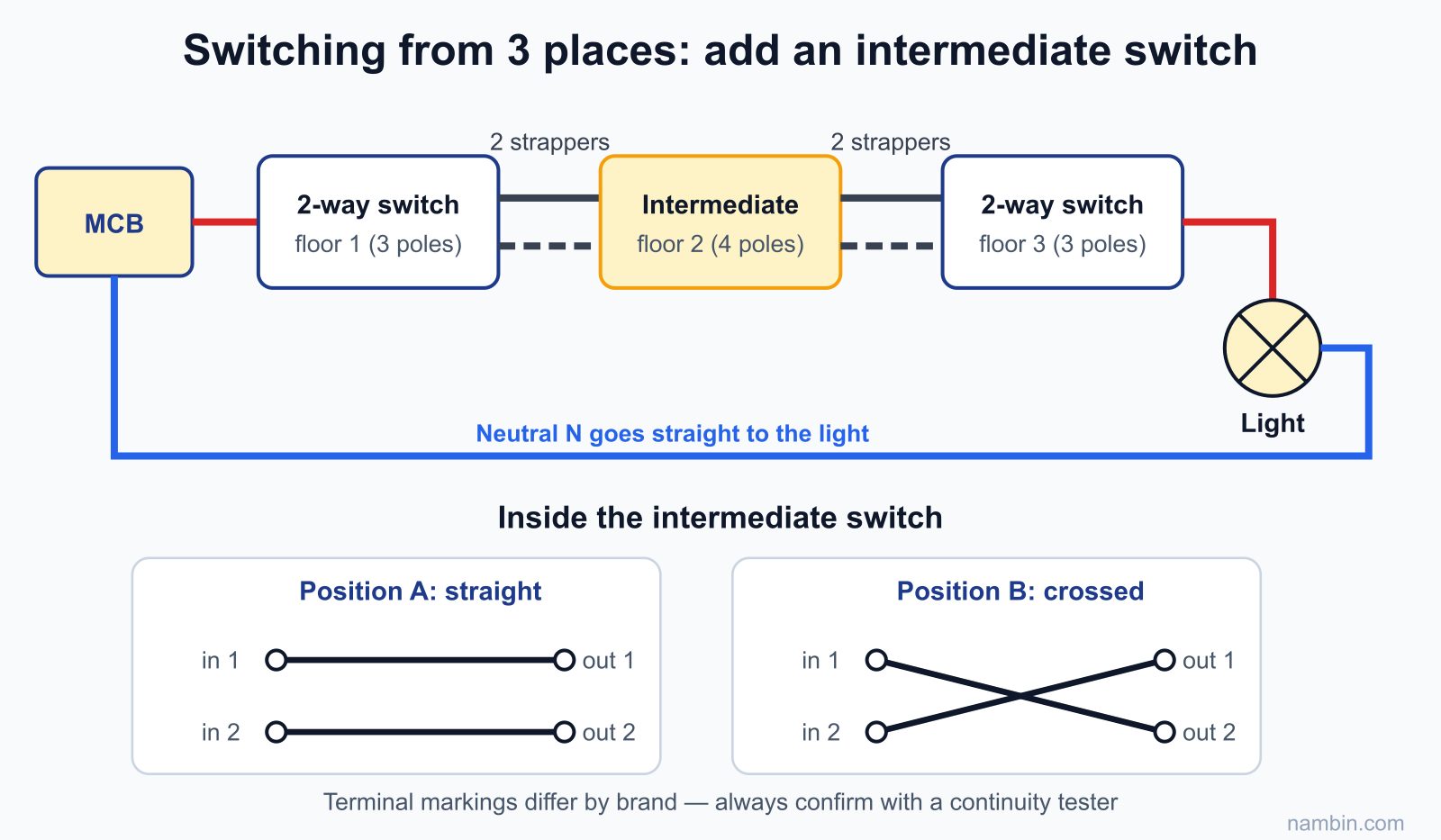
Owners of a 3-storey tube house (the narrow, deep townhouse common in Vietnam) often want to switch the stair light on and off from the 1st, 2nd and 3rd floors. The method: the two ends remain two-way switches, and in the middle you insert an intermediate switch (also called a crossover switch, with 4 terminals). The two strappers from the first switch go into the "in" pair of terminals, and the two strappers continuing to the last switch leave from the "out" pair. In one position the intermediate switch connects straight through (in 1 – out 1, in 2 – out 2); in the other it crosses over (in 1 – out 2, in 2 – out 1). To add a fourth position, insert another intermediate switch. Terminal markings differ between manufacturers, so always read the diagram printed on the back of the switch and confirm it with a continuity tester.
Earthed sockets
Three wires go to three terminals: live (L), neutral (N) and earth (marked with the earth symbol or PE). Choose one L – N position convention for the whole building and record it on the as-built drawing. With several sockets on the same circuit, connect them in parallel using joints in a box or a secure loop at the socket terminal; avoid letting the earth wire "borrow" the socket terminal on its way through, because when one socket is removed for repair, all sockets after it lose their earth.
Sockets for high-power or wet-area appliances (water heaters, washing machines, cookers, outdoor sockets) should have their own circuit from the consumer unit, with 30 mA residual current protection — the layout of protective devices is covered in the next step on the consumer unit.
Tools, materials and reference values
Prepare: wire strippers, side cutters, insulated screwdrivers, a voltage tester pen, a multimeter, an insulation resistance tester (megger), a conduit bending spring, a tape measure, a drill and a wall chaser. Materials: rigid or flexible corrugated conduit, junction boxes, flush back boxes, twist-on connectors or push-in/lever terminal connectors, and flexible single-core cable of the right size.
| Item | Common reference practice | Notes |
|---|---|---|
| Lighting circuit cable | 1.5 mm² | See the lesson on choosing cable size and breakers |
| General socket circuit cable | 2.5 mm² | High-power appliances should have their own circuit |
| Conduit fill | Total cable cross-section ≤ about 40% of the conduit's inner cross-section | A tight conduit is hard to pull and hard to rewire later |
| Switch height | About 1.2–1.4 m above the finished floor | Consistent throughout the house, as per the drawing |
| Socket height in living rooms | About 0.3–0.4 m | Kitchen and washing-machine sockets higher, away from splashes |
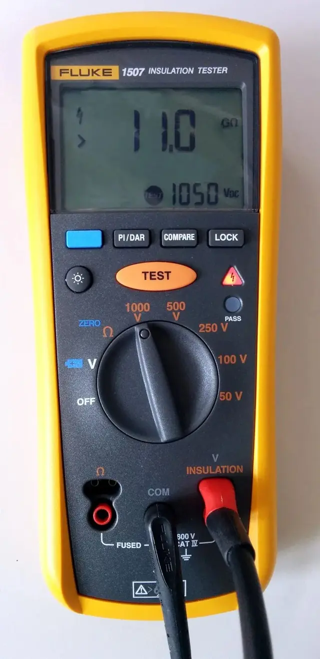
| Insulation resistance (220 V circuit) | ≥ 1 MΩ when tested at 500 V DC | Newly installed circuits usually read much higher |
Choosing connectors and terminal blocks
Every twist-on connector and push-in terminal states the allowed cable size range and number of conductors on its body or packaging. Choose the right range: a connector that is too big leaves the wire loose, one that is too small forces you to cut strands — both increase contact resistance. With screw terminals, crimp a pin ferrule onto stranded flexible cable before tightening the screw so the copper strands do not splay out.
Choosing conduit
Rigid conduit is for straight runs in walls and ceilings; flexible corrugated conduit is for bends and the final run into a light, but do not overuse it, because the ribbed inner wall makes pulling cable harder. For sections buried in the floor or under load, use stronger conduit as specified in the drawing.
Worked example: stair light in a 3-storey tube house
Requirements and counting wires
The owner wants one light on the landing between the 1st and 2nd floors, switchable at the foot of the stairs on the 1st floor and at the top of the stairs on the 2nd floor. The circuit uses 1.5 mm² cable from the 1st-floor lighting breaker. Count the wires for each conduit run:
- 1st-floor lighting junction box → 1st-floor switch: 1 live wire.
- 1st-floor switch → 2nd-floor switch: 2 strapper wires.
- 2nd-floor switch → light: 1 switched wire to the light.
- Junction box → light: neutral and earth (a metal-bodied light needs PE). If they share a conduit with the switched wire, this run carries 3 wires — the most crowded run.
Checking conduit fill
Suppose you use 16 mm round conduit with an inner diameter of about 13 mm. The inner cross-section ≈ 3.14 × 6.5² ≈ 133 mm²; 40% is about 53 mm². Single-core 1.5 mm² cable has an outer diameter of about 3 mm including insulation, taking ≈ 3.14 × 1.5² ≈ 7 mm² per wire. Three wires take about 21 mm² — plenty of spare room, even for replacement cable later. If the same conduit must also carry a 2.5 mm² socket circuit (outer diameter about 3.6–4 mm, about 10–12 mm² per wire), the total easily exceeds 53 mm²; in that case use a separate conduit or a 20 mm one. Actual outer diameters vary between manufacturers, so measure them or check the catalogue of the cable you use.
Testing after installation
Before switching on: test continuity from the common terminal of the 1st-floor switch to the common terminal of the 2nd-floor switch in all four combinations from the table above — continuity in two combinations, open in the other two. After switching on: test all four combinations, and each time the light is off, touch the tester pen to both contacts of the lamp holder — it must not show live.
Step-by-step installation procedure
The order below applies to a house under construction or a renovation where walls are chased. The first seven steps are done entirely with no power; only the last step turns the breaker on.
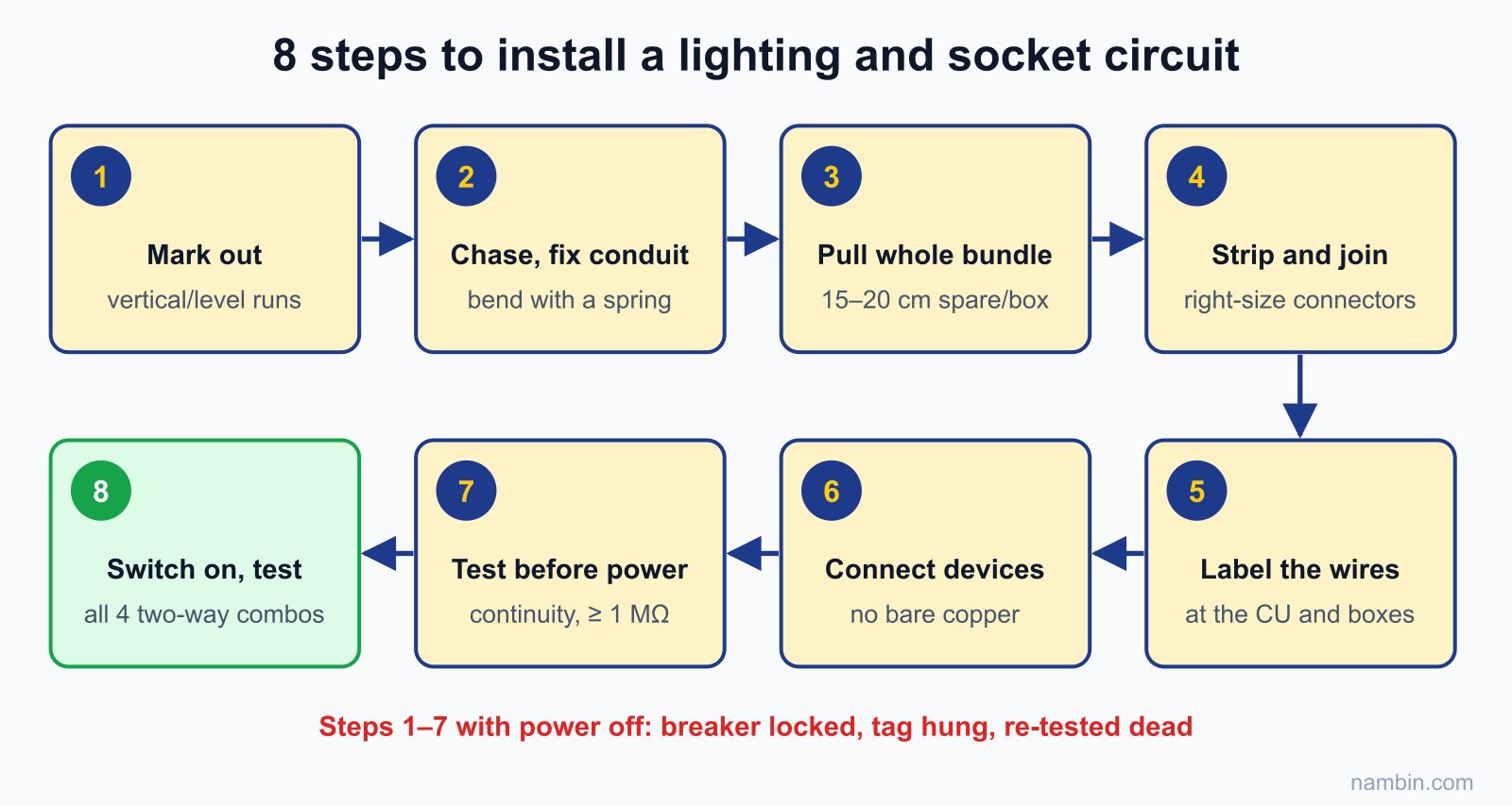
- Mark out positions: following the drawing, mark the lights, switches, sockets and junction boxes. Conduit runs go vertically or horizontally, never diagonally across a wall — so whoever drills the wall later can guess where the cable is.
- Chase the wall and fix the conduit: the chase must be deep enough for the plaster to cover the conduit completely. Bend conduit with a spring, never kink it. Fix the conduit and back boxes firmly, with the box face flush with the finished wall surface.
- Pull the cable: pull the whole bundle at once with a draw wire, rather than one wire at a time, which scratches the insulation. Leave about 15–20 cm spare at each box for connections.
- Strip and join: strip just enough to fit the terminal without cutting core strands. Make joints in the box with connectors or push-in terminals of the right size; tighten screws firmly and tug each wire to test it.
- Label the wires: label them at the consumer unit and in the junction boxes: circuit name, strapper wires, switched wire to the light.
- Connect the devices: switches, sockets, lamp holders. Do not leave bare copper outside a terminal. Fold the wires neatly into the box before fixing the faceplate.
- Test with the power off: continuity of each run, check that switches break the live wire, measure insulation resistance between conductors and between each conductor and earth.
- Switch on and test function: operate every switch in every position, use the tester pen to confirm the lamp holder is not live when off, and check that every socket is live and correctly polarized.
Safety: All cable running, connection and insulation testing is done only when the circuit is switched off, the breaker locked off, a warning tag hung and the circuit re-tested as dead. When testing with a megger, remove LED lamps, drivers and electronic devices from the circuit — the test voltage can damage them — and do not touch the wires during the test, because the megger produces a high voltage.
Tips for pulling cable without scratching the insulation
Blow or feed the draw wire in before plastering, not after. Tie the cable ends to the draw wire staggered and wrap them in tape into a tapered point, so the bundle does not jam at bends. One person feeds and one pulls evenly; if it feels unusually heavy, stop and check the bend instead of yanking.
Tips for correct insulation testing
Test circuit by circuit and record the test conditions: lamps removed, which position each switch was in. For a circuit with two-way switches, test twice in the two switch positions so both strapper wires are checked. When you finish, discharge the remaining voltage on the wires as the tester's instructions say before touching them.
Tips for testing sockets after switching on
Use a meter to measure voltage L – N (about 220 V), L – PE (about 220 V) and N – PE (close to 0 V). If L – PE is close to 0 V while L – N is normal, the earth wire is not continuous back to the consumer unit, or there is no earthing system yet — record it and tell the owner.
Common mistakes and how to avoid them
Most installation mistakes do not make the circuit "fail" straight away, so they easily slip through handover if you only switch on a few times. The figure below summarizes the four most common right/wrong pairs; the list after it explains how to recognize and avoid them.
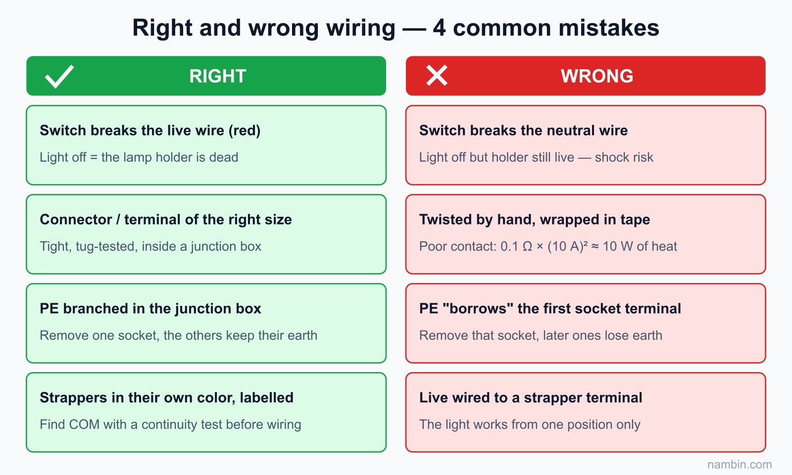
- Joining wires by twisting by hand and wrapping with tape: poor contact that heats up over time. Use connectors or terminals of the right size.
- A switch that breaks the neutral: the light still turns off normally, so it is hard to spot. Always test the lamp holder with a tester pen with the switch off.
- Mistaking the common terminal of a two-way switch: identify it with a meter before wiring; do not guess from terminal position.
- Leaving out the earth wire because "the house has no earth rod yet": still run the PE wire to every socket and back to the consumer unit; tell the owner that an earthing system needs to be made in the next step.
- Placing a socket right next to a tap or sink: keep a safe distance, use sockets with covers in damp areas and protect them with a residual current device.
- Running strappers in the same color as live: sign — a later electrician mistakes a strapper for the supply live and wires it wrongly. Prevention — use a different color or label both ends.
- Back boxes set too deep behind the plaster: sign — the switch plate does not sit tight when screwed, the socket wobbles when a plug is pulled out. Prevention — align the box face to the finished level as you fix the conduit, and use box spacers if it is already too deep.
Frequently asked questions
Can I use a two-way switch instead of a one-way switch?
Yes. Use only the common terminal and one strapper terminal, leaving the other empty. Many electricians do this to keep all switch plates in the house the same and to make upgrading to two-way easy later.
The light works from both places but sometimes needs two flicks to come on — why?
Usually one strapper wire is loose or broken: the circuit has only one path left, so only two of the four combinations work correctly. Switch off and test the continuity of each strapper between the two switches.
The house has no earth rod yet — should I still fit 3-pin sockets?
Yes, fit 3-pin sockets and run the full PE wiring back to the consumer unit, but tell the owner clearly that the earth does nothing until a rod is installed and connected to the PE bar. Write this in the handover report.
Should a socket circuit be radial or looped from socket to socket?
Both work if the joints are secure and the cable is the right size. Looping from socket to socket saves cable, but every joint is a point that can fail and affect the sockets after it; sockets for large appliances should have their own run.
Can I just wrap a joint in electrical tape?
Tape is only extra insulation; it cannot replace a connector or terminal. A joint must be mechanically sound first and insulated second.
Handover checklist and exercises
- Every switch breaks the live wire; the lamp holder is not live when off.
- The two-way switches control the light from both positions, in every combination.
- Every socket has L, N and PE; the earth wire is continuous to the consumer unit.
- Insulation resistance of each circuit meets the requirement, with readings recorded.
- Joints are in boxes with removable covers; wires are labelled.
- Exercise: on a wooden practice board, install a circuit with a breaker, 1 one-way switch, 2 two-way switches controlling 1 light, and 2 earthed sockets. Record the continuity and insulation readings on a one-page report.
- Advanced exercise: add an intermediate switch to control the light from three positions, and draw up a test table for all eight combinations.
Self-assessment criteria:
- Complete the basic circuit in about 2 hours, re-wiring no more than once.
- Tug each wire at the connectors — none pulls out; no bare copper outside any terminal.
- Wire colors follow the convention; strappers have their own color or label.
- The readings table includes continuity for all four two-way combinations and insulation resistance for each circuit, with the test voltage.
- You can explain in words why a switch must break the live wire and why the light changes state whichever switch you flick.
Once the branch circuits are installed, the next step in the roadmap is The home consumer unit: MCB, RCBO and earthing — where all the circuits you have just wired are protected and connected to a safe earthing system.