Customers rarely call a plumber because of a leaking pipe. They call because "the pump runs forever but no water comes up", "the top floor has weak pressure" or "the water heater leaks and my hand tingles when I touch it". All three problems sit in the same group of equipment — the pump, the rooftop tank and the water heater. Installing this group wrongly can burn out the pump, collapse the tank stand or cause an electric shock in the bathroom.
By the end of this lesson, you will be able to:
- Draw and explain the water supply diagram of a Vietnamese townhouse: underground tank → pump → rooftop tank → floors, and know when a booster pump is needed.
- Calculate head and flow to choose a pump, and install it with a check valve, a float switch or pressure switch, and dry-run protection.
- Install a stainless steel rooftop tank with the correct stand, valves, sediment drain, overflow and vent.
- Make the water connections for a storage water heater with a safety valve, and coordinate with the electrician on the residual current breaker and earthing.
- Carry out routine maintenance and diagnose the common faults of pumps, tanks and water heaters.
The townhouse water supply: which way does the water go?
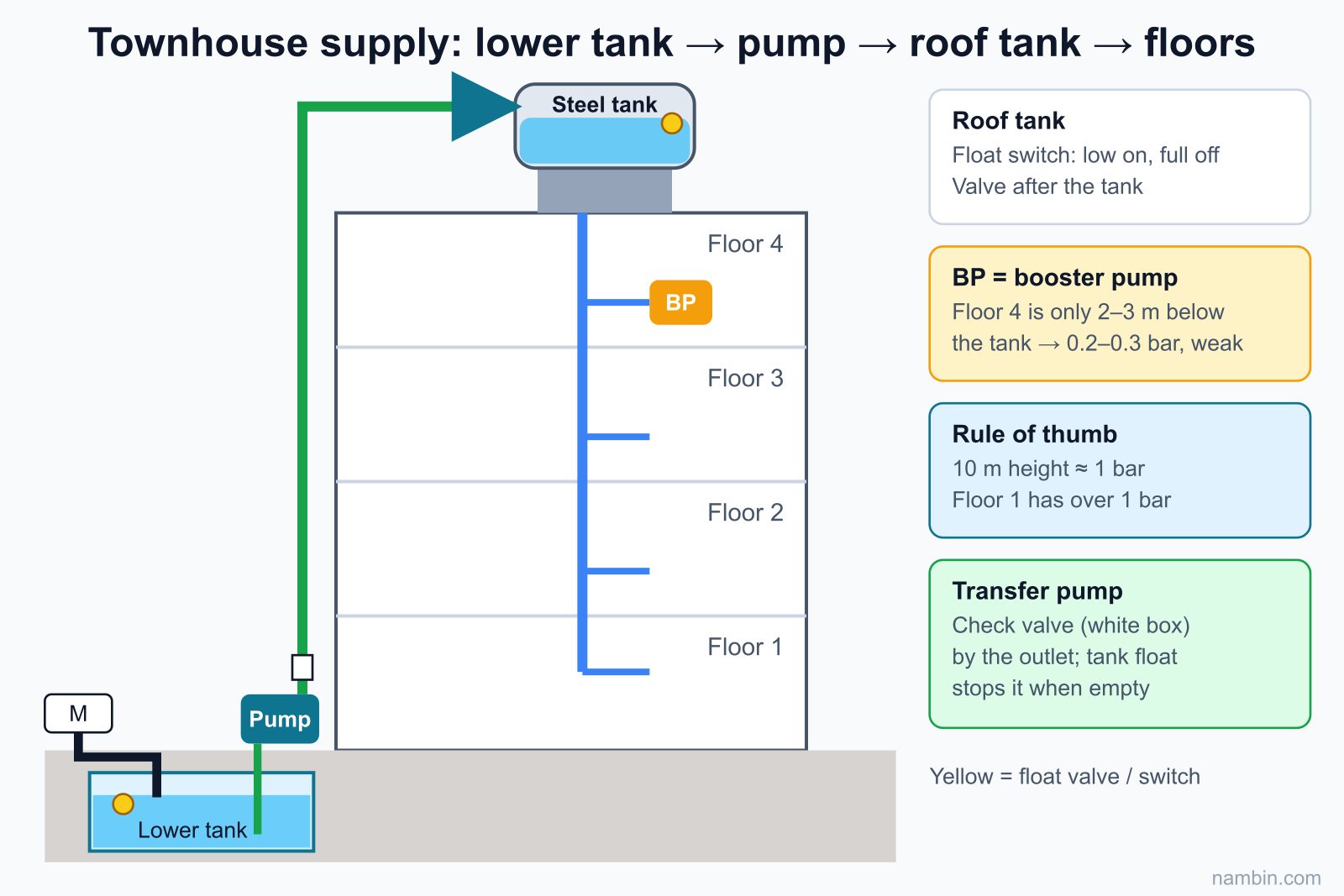
Most townhouses in Vietnam use an "underground tank – pump – rooftop tank" layout: mains water from the meter flows into an underground tank (or a tank on the ground), a pump pushes it up to the rooftop tank, and from there water flows down to each floor by gravity (see Figure 1).
Why not pump straight from the city main?
Mains pressure in many residential areas varies through the day, and at peak times it may not even reach the second floor. The underground tank acts as a "buffer store": mains water trickles in day and night through a mechanical float valve, and the pump draws from the tank up to the roof. Pumping directly from the shared main lowers the pressure for the neighbours and is not allowed in many places.
Pressure depends on the height of the tank
Remember the rule: every 10 m of height difference gives about 1 bar (1 m of water column ≈ 0.1 bar). In a 4-storey house, the rooftop tank sits on a stand, but the bottom of the tank is only about 2–3 m above the fourth-floor shower head, so that shower gets only 0.2–0.3 bar — very weak. Meanwhile the ground-floor shower is more than 10 m below and gets over 1 bar. That is why the top floor usually needs a booster pump after the rooftop tank, while the lower floors are fine on gravity.
Transfer pump versus booster pump
- Transfer pump (tank-filling pump): lifts water from the underground tank to the rooftop tank. It needs a high head and is controlled by float switches: it runs when the roof tank is low and stops when it is full.
- Booster pump: installed after the rooftop tank to raise the pressure for the top floor or the whole house. It is controlled by a pressure switch or flow sensor: it runs when a tap opens and stops when the tap closes.
Never use a booster pump with a pressure switch to fill an open rooftop tank — an open tank never builds pressure, so the pump runs non-stop.
Choosing a pump: head, flow and power
Choosing a pump by its "horsepower" (HP) is the most common mistake. The two figures you must calculate are the head H (metres) and the flow Q (litres/minute or m³/hour). Then read the pump curve in the catalogue to choose a pump whose operating point fits.
Worked example: a 4-storey tube house
Situation: a 4-storey tube house (a narrow, deep townhouse), each floor 3.6 m high, an underground tank 2 m below the ground floor, a 1500-litre stainless tank on a 1.2 m stand on the roof terrace, with the tank inlet about 1.3 m higher still. Five people live there.
| Component | How it is calculated | Value |
|---|---|---|
| Suction lift | Lowest water level in the tank to the pump shaft | ≈ 2 m |
| Height of 4 floors | 4 × 3.6 m | 14.4 m |
| Stand + tank inlet | 1.2 + 1.3 m | 2.5 m |
| Static head | 2 + 14.4 + 2.5 | 18.9 m |
| Losses in pipes, elbows and valves | Add about 20–25% | ≈ 4–5 m |
| Required head | ≈ 23–24 m |
Flow: to fill the 1500-litre tank in about 40 minutes you need Q ≈ 1500 ÷ 40 ≈ 38 litres/minute (≈ 2.3 m³/hour). Look for a pump that still delivers about 35–40 litres/minute at a head of 24 m. For houses, this is typically a 370–750 W pump with a maximum head of 30–40 m — but you must read the curve for each specific model.
Estimating the tank size
A reference figure for domestic water use is about 120–150 litres per person per day. A household of five uses about 600–750 litres a day, so choose a 1000–1500-litre tank to have a reserve if power or mains water is cut for a day. A tank that is too big keeps water standing for too long and builds up sediment.
Mistakes when choosing a pump
- Choosing a pump whose maximum head equals the required head: at that point the flow is almost zero, so the pump runs forever without filling the tank.
- Choosing a pump that is too big: short cycles, constant switching on and off, wasted electricity and early failure of the relay and capacitor.
- Forgetting the suction lift: a normal centrifugal pump can only lift a few metres on the suction side; a deeper tank needs the pump placed lower or a submersible pump.
Installing the pump correctly
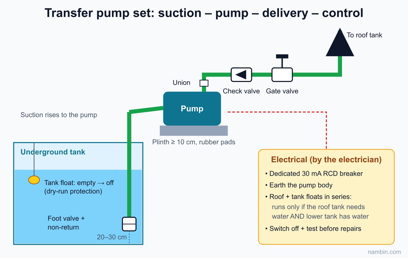
A standard transfer pump set consists of: a foot valve strainer with a non-return valve at the end of the suction pipe, a short airtight suction pipe, the pump on a plinth, unions on both sides, a check valve and a gate valve on the delivery pipe, and a control circuit with a float switch for dry-run protection (see Figure 2).
Materials and tools
Pump and plinth with rubber anti-vibration pads; foot valve strainer with non-return valve, a suction pipe the same size as or larger than the pump inlet; check valve, gate valve, two unions, PPR/HDPE pipe for the delivery line; electric float switches for the underground and rooftop tanks; PTFE tape, spanners and a PPR welding machine.
Installation steps
- Place the pump on a dry plinth at least 10 cm above the floor, under a cover against rain and sun, with ventilation so the motor can cool; put rubber pads under the pump feet.
- Install the suction pipe: the foot valve sits about 20–30 cm above the tank bottom so it does not suck up sediment; keep the suction pipe as short as possible with as few elbows as possible; the horizontal section must rise steadily towards the pump, with no humps that trap air.
- Install the delivery side: right after the pump outlet comes a union, then the check valve, then the gate valve. The check valve holds the water column in the riser when the pump stops, preventing backflow that spins the impeller backwards and loses the prime.
- Support the pipes with their own clamps; never let the weight of the pipework rest on the pump body.
- Prime the pump: open the priming plug, fill the pump body and suction pipe with water until no air bubbles remain, then tighten the plug.
- The electrician connects the power and the float switches; you check the direction of rotation, listen to the sound and time how long the pump takes to fill the tank compared with your calculation.
Float switches, pressure switches and dry-run protection
A transfer pump normally uses two electric float switches wired in series: the rooftop tank float (closes when the tank is low, opens when it is full) and the underground tank float (opens when the tank is empty). The pump only runs when the roof tank needs water and the underground tank still has water. Without the underground tank float, the pump runs dry when the mains is cut, and the mechanical seal burns out within a few tens of minutes.
A booster pump uses a pressure switch (with cut-in and cut-out settings, for example cutting in at about 1.5 bar and out at about 2.5–3 bar depending on the type) or a flow sensor. Choose a model with built-in dry-run protection, or add a protection unit. The cut-out pressure must be lower than the permitted working pressure of the water heater and other appliances downstream.
Electrical safety: A pump in a damp location carries a high risk of electric shock. The electrical work (a 30 mA RCBO/ELCB residual current breaker, the supply cable, earthing the pump body, wiring the float switches) must be done by an experienced electrician. Before removing or repairing the pump: switch off the breaker, hang a "Work in progress" sign and check again with a voltage tester. Never touch the pump, floats or cables while standing in water.
Installing the stainless rooftop tank
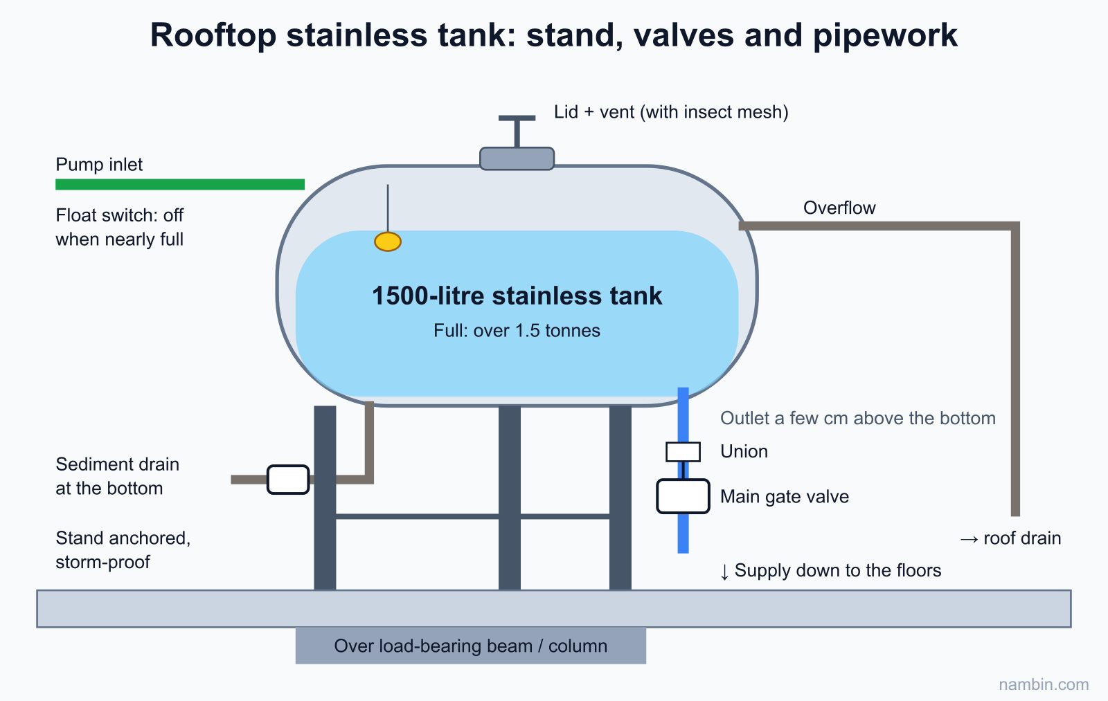
A 1500-litre tank weighs more than 1.5 tonnes when full, sits high up and faces storms. So the most important part of installing a rooftop tank is the stand and its location; the valves and pipes come after that (see Figure 3).
Stand and location
- Place the tank where there is a load-bearing beam or column underneath; never in the middle of a thin slab span or on a sheet-metal roof. If unsure, ask a structural engineer or ask the homeowner for the drawings.
- Use the stand designed for the tank, with a flat bearing surface checked with a spirit level; the tank must sit neatly on the stand without rocking.
- Anchor the stand to the slab with expansion bolts or a concrete plinth, especially in storm-prone areas.
The tank connections and how to make them
- Inlet (at the top): the pipe from the pump. If the tank is fed directly by mains water with enough pressure, fit a mechanical float valve here.
- Outlet: the outlet pipe inside the tank stands a few centimetres above the bottom, so sediment settles and does not flow down into the house. After the outlet come a union and the main gate valve — handy for shutting off during repairs.
- Sediment drain at the bottom, with its own valve, piped to the roof drain; to flush the tank you only need to open this valve.
- Overflow pipe piped to the roof drain — in case the float fails, water will not spill over the lid onto the roof terrace or down the walls.
- Vent: the tank lid has a vent hole (with a mesh). Never seal the lid; a sealed tank creates a vacuum as the water level drops, which can dent the tank and weaken the flow.
Water test and tank acceptance
Run the pump until the tank is full and check that the float stops it at the right level (water a few centimetres below the overflow). Check for leaks at the threads and unions, then open a tap on the lowest floor and check that the pump restarts at the right moment. Re-check the stand once the tank is full: no sinking, no tilting.
Installing a storage water heater
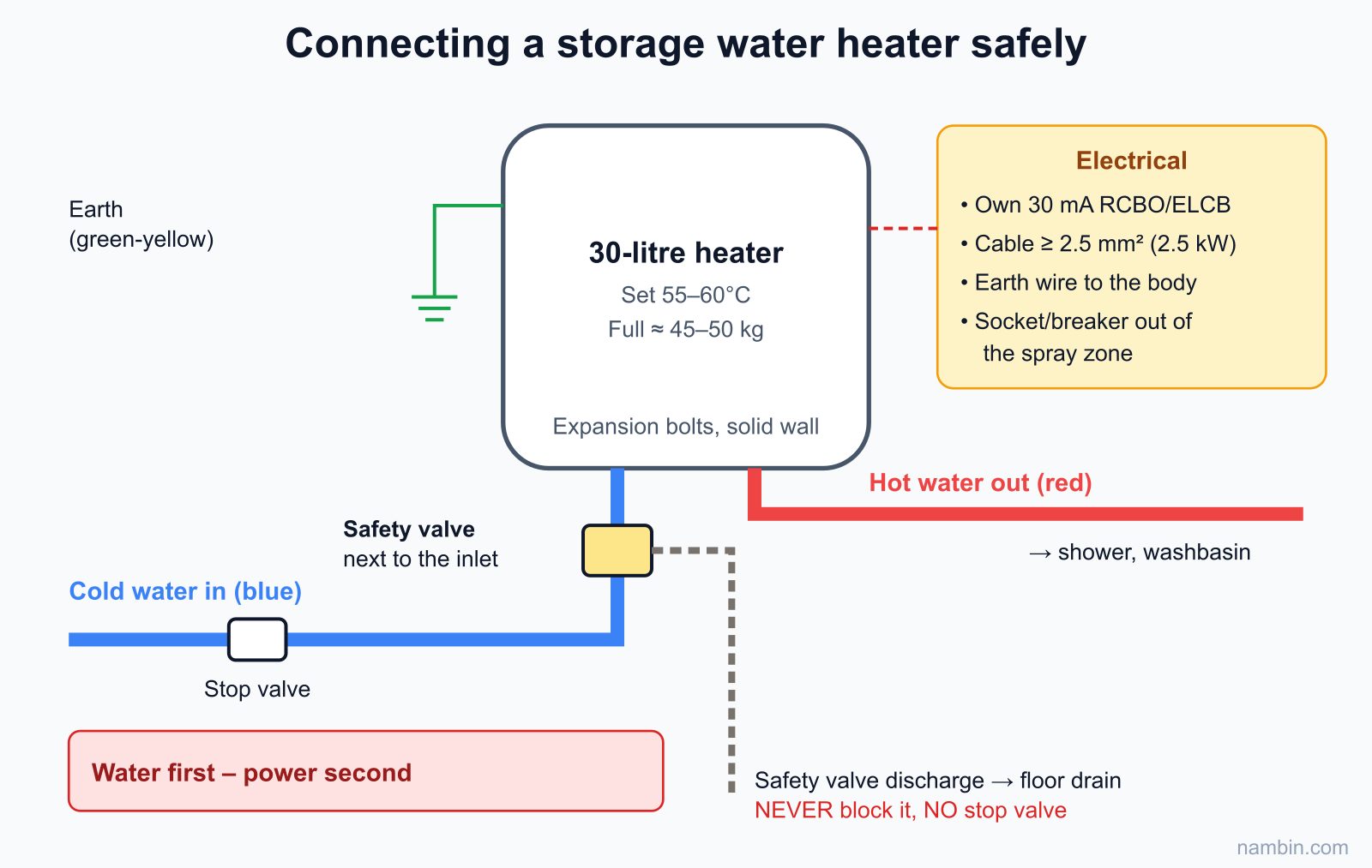
A storage water heater (typically 15–30 litres) heats water inside the tank and supplies it to the shower and washbasin. It combines water + electricity + pressure + heat, so every connection detail is a safety matter (see Figure 4).
Location and mounting
- Hang it on a solid brick or concrete wall with expansion bolts rated for the load; a 30-litre heater weighs about 45–50 kg when full. Never hang it on plasterboard or hollow blocks without a support frame.
- Keep it out of the direct spray of the shower, and leave space to replace the magnesium anode and remove the heater.
- Keep the hot pipe from the heater to the shower as short as possible to reduce heat loss and the time spent running off cold water.
Water connections: cold blue in, hot red out
- Identify the ports: heaters usually have a blue ring for cold water in and a red ring for hot water out. Connecting them the wrong way round gives very little hot water and the heater can overheat.
- Cold inlet line: stop valve → safety valve (a non-return valve with pressure relief, supplied with the heater) → blue port. Fit the safety valve as close to the heater as possible, with the arrow pointing the right way.
- Never fit a stop valve between the safety valve and the heater, and never block the safety valve's discharge hole. As hot water expands, the pressure in the tank rises; the safety valve releases a few drops so the tank does not bulge or burst.
- Connect a small flexible tube from the safety valve outlet down to the floor drain, so the normal dripping while the heater is heating does not wet the wall.
- Hot outlet line: red port → PPR PN20 pipe (or heat-resistant stainless braided hose) → the hot water outlets.
- If the house has a booster pump or the supply pressure is higher than the working pressure printed on the heater (usually 6–8 bar), add a pressure reducing valve on the inlet line.
Working with the electrician: residual current protection and earthing
The electrician does the electrical work, but you must know enough to check it. A 2500 W heater at 220V draws about 2500 ÷ 220 ≈ 11.4 A, so it needs:
- A dedicated circuit from the distribution board with a 30 mA RCBO or ELCB residual current breaker, rated at about 16–20 A depending on the heater power.
- Copper cable of at least about 2.5 mm² for a 2.5 kW heater (the electrician recalculates for the cable length and installation method).
- An earth wire connected to the heater body and back to the house earth rod. The residual current breaker protects people; the earth carries leakage current to the ground — you need both.
- Switches and sockets placed out of the spray zone, high and dry, with covers if they are inside the bathroom.
First start-up
Always water first, power second: open the supply valve and open the hot tap at the shower until the water flows steadily with no more spluttering air — only then is the heater full. Close the tap, check every joint for leaks, and only then switch on the power. If you switch on before the tank is full, the heating element burns out dry within minutes. Set the temperature to about 55–60°C: hot enough, limits bacteria, causes less scale and less risk of scalding than the maximum setting.
Electrical and hot water safety warning: Never install or repair a heater without first switching off the breaker. Never use a heater when the residual current breaker has been removed or bypassed, or when it does not trip when you press TEST. If touching the tap or shower gives a tingling feeling, switch off the power immediately and call an electrician — this is a sign of electrical leakage and can be fatal. Water above 50°C can scald young children and the elderly within seconds; always open the cold water first, then add hot.
Routine maintenance for the pump, tank and heater
You can print the reference schedule below and leave it with the homeowner — it is also a service that helps you keep customers for the long term:
| Item | What to do | Reference interval |
|---|---|---|
| Pump | Listen to it running, check for seal leaks, clean the foot valve strainer, check the floats | 3–6 months |
| Underground tank | Flush and clean, check the lid seals, check the mechanical float valve | 6–12 months |
| Rooftop tank | Open the sediment drain, flush the inside, check the stand and the vented lid | 6–12 months |
| Water heater | Drain sediment from the bottom, check that the safety valve still drips while heating | 6–12 months |
| Magnesium anode in the heater | Check how much it has worn, replace when heavily worn | 1–2 years (sooner with hard water) |
| Residual current breaker | Press TEST; the breaker must trip | Monthly |
Flushing the rooftop tank properly
Close the tank outlet valve, switch off the pump and open the sediment drain so the dirty water runs out to the roof drain. Scrub the inside with a soft brush; do not use wire brushes or harsh chemicals that damage the stainless steel. Rinse with clean water, close the drain valve and switch the pump back on.
Draining sediment from the water heater
Switch off the power, wait for the water to cool, close the cold supply valve, open a hot tap to release the pressure, then drain the water as the manufacturer instructs (through the drain valve or by disconnecting the cold inlet). When reconnecting, remember the rule: fill with water before switching on the power.
Common faults and how to fix them
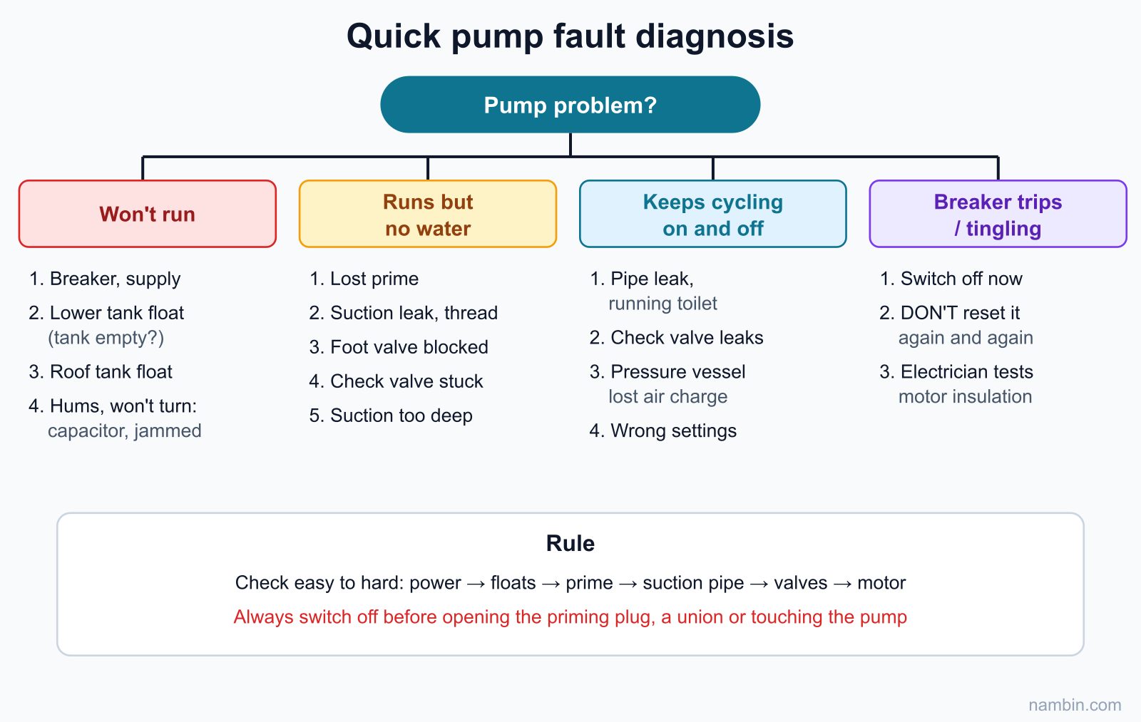
When a customer reports "no water", follow the water path from the roof tank back to the underground tank while watching the pump and floats. The diagram below helps you check in the right order (see Figure 5).
The pump runs but no water comes up
Symptom: the pump hums steadily but the tank does not fill, and the pump body gets hot. Cause: loss of prime because the foot valve is jammed with debris or leaking; air leaking into the suction pipe at a thread; an air pocket in the suction pipe; an empty tank. Fix: switch off the pump, check the tank level, clean the foot valve, re-tape the suction-side threads and re-prime. A pump that has run dry for a long time needs its seal checked.
The pump keeps switching on and off
Symptom: with a booster pump, nobody is using water but the pump runs for a few seconds and stops, again and again. Cause: a leak somewhere in the house (a running toilet, a dripping tap), a leaking check valve, or a pressure vessel that has lost its air charge. Fix: close the branch valves one by one to locate the leak, replace the check valve, and re-pressurise the pressure vessel to the pressure the manufacturer specifies.
The water heater leaks or does not heat
Leak at a connection: usually not enough PTFE tape on the thread or a poor-quality hose — replace the hose and re-tape the thread. Leak from the tank body: the inner tank has corroded through, often because the magnesium anode was never replaced; tell the homeowner the heater must be replaced. No heat: check the indicator light and the breaker; if the power is fine, the heating element and thermostat are a job for the electrician or the manufacturer's warranty service.
Frequently asked questions
Can I use one booster pump for the whole house instead of a rooftop tank?
Yes, when the water supply is stable and the house has few floors. But a power cut means no water straight away, and the pump runs many times a day. Most townhouses still keep a rooftop tank as a reserve.
Is a dripping water heater safety valve faulty?
No. While the heater is heating, the water expands and the valve releases a few drops — that is normal. If the valve runs in a steady stream even when not heating, the supply pressure may be too high (a pressure reducing valve is needed) or the valve may be clogged with scale — clean it or replace it with the same type.
Can I wire the pump and heater myself?
If you have not been trained and have no experience with electrical work, leave it to an electrician. You are responsible for the plumbing and for re-checking the safety points: there is a residual current breaker, there is earthing, no cables run through the spray zone and the TEST button works.
Practical exercises and self-check
Exercises
- Calculate the required pump head for a 5-storey house with floors 3.5 m high, an underground tank 1.5 m deep, a stand plus tank inlet of 2.5 m, and 25% added for losses.
- Draw the water supply diagram of your own house (or the example house in this lesson): mark the tank, pump, check valve, floats, rooftop tank, the gate valve after the tank and the booster pump if there is one.
- Under the guidance of a master plumber, assemble a water heater connection set on a practice board: stop valve, safety valve, cold line, hot line and the safety valve discharge pipe.
- Draw up a 12-month maintenance schedule for a townhouse with a transfer pump, a booster pump, a 1500-litre tank and two water heaters.
Self-assessment criteria (pass / not yet)
- Exercise 1: static head = 1.5 + 17.5 + 2.5 = 21.5 m; adding 25% ≈ 27 m. You understand that you must choose a pump that still delivers enough flow at 27 m, not a pump with a maximum head of 27 m.
- The diagram has a check valve right after the pump, an underground tank float for dry-run protection and a gate valve after the rooftop tank.
- Water heater set: cold goes into the blue port through the safety valve, there is no stop valve between the safety valve and the heater, and the discharge pipe runs to the floor drain.
- You can explain three safety points to the homeowner: 30 mA residual current protection, earthing, and water first – power second.
Next step in the roadmap (step 7 — Repairing common leaks and blockages): now that you understand the whole supply system from the underground tank to the water heater, you will move on to real repair jobs — dripping taps, leaking concealed joints, blocked washbasins, toilets and floor drains — learning to diagnose, repair and record before-and-after reports for the customer.