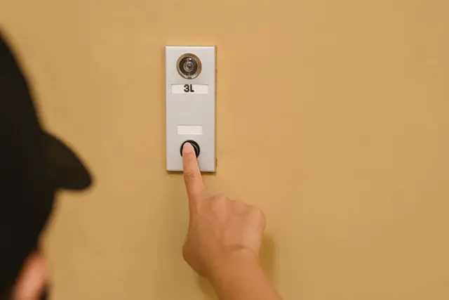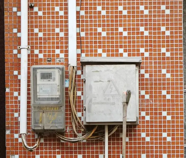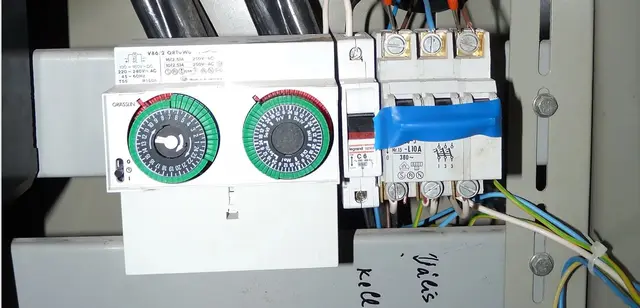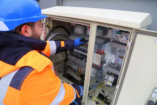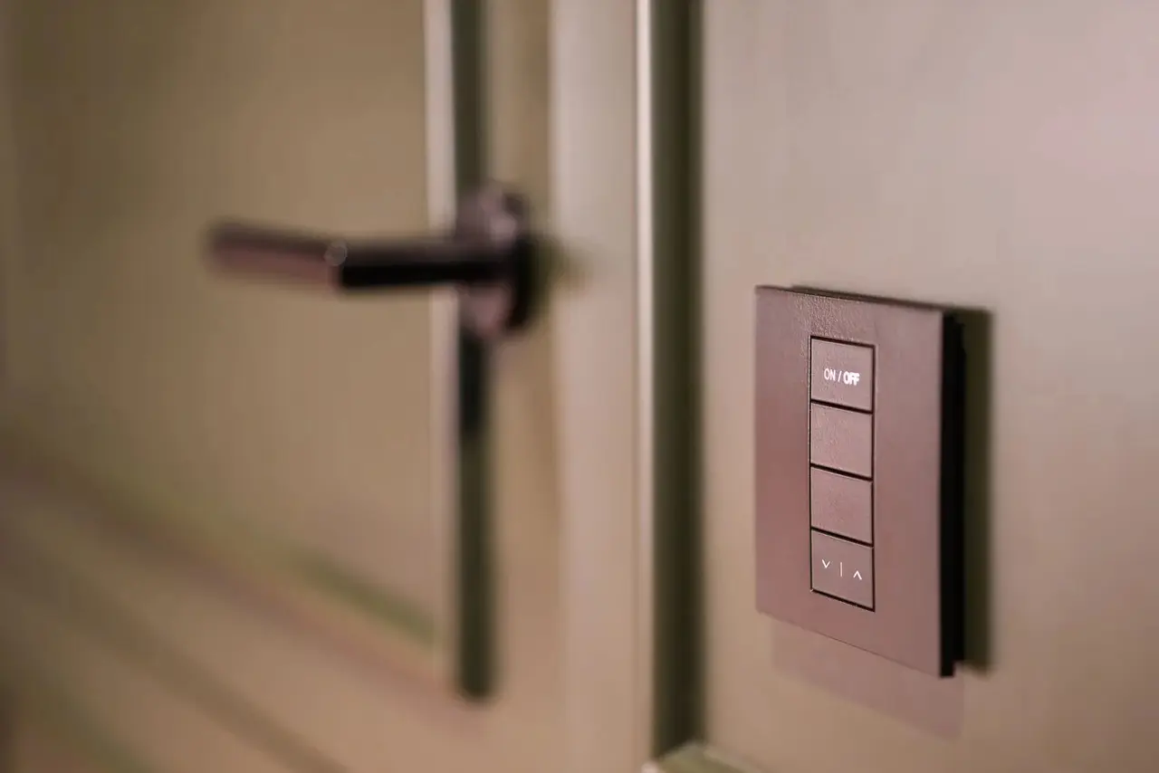
A client shows you a glass touch switch they bought online. The box says "Wi-Fi smart switch, 3 gang, works with phone app". They want it in place of the old switch by the living-room door, so they can turn the lights off from bed. You take off the old switch plate and find just two wires behind it. Will the new switch work?
Maybe not. Fitted wrongly, it can leave LED lights glowing at night, a switch that keeps rebooting, or a dangerous "borrowed" neutral in the wall. A smart switch is a small electronic device that must stay powered all the time, and that changes how you choose and wire it.
This guide covers the whole job: how smart switches get their power, checking for a neutral safely, your options when there is none, wiring, pairing, testing and fixing common faults such as flicker.
Scope of this guide. This article is for trainee and working residential electricians on single-phase 230 V / 50 Hz supplies, as used in Vietnam. Wiring of fixed installations should only be done by a competent person, following local regulations and the switch manufacturer's instructions. Terminal names, ratings and wiring diagrams differ between brands, so the diagram printed on or supplied with the product always comes first. Any dimensions or figures below are for reference only.
How a smart switch differs from a normal switch
A normal wall switch is just a gap in the live conductor and uses no power. A smart switch contains a small power supply, a Wi-Fi (or other radio) chip, touch sensors, indicator LEDs and an output that switches the lamp, usually a relay or an electronic switch such as a triac. The electronics must stay powered even when the light is off, so the switch needs its own current path. There are two ways to get it:
Switch with neutral. The switch is connected to the live feed (L) and to the neutral (N), so its electronics have their own supply, exactly like any other appliance. The output simply switches live to the lamp. This is the most reliable design.
No-neutral switch (sometimes sold as "single live wire"). The switch has only L in and the lamp wire out. When the light is off, it powers itself by passing a very small current through the lamp to neutral. An incandescent bulb shows nothing, but an LED lamp may glow faintly or flash every few seconds.
This difference explains most "smart switch LED flickering" and "smart switch keeps disconnecting" problems.
Know the terminals before you buy
Read the label on the back of the switch and the diagram in the box. Common markings include:
L (sometimes L-in, COM or "Line"): the incoming live feed from the circuit breaker.
N: neutral. Present on switches that need a neutral.
L1, L2, L3 (sometimes "Load", "1, 2, 3" or arrows): the switched outputs, one per gang, each going to a light or group of lights.
S1, S2 on in-wall relay modules: inputs for an ordinary push button or rocker switch.
Earth terminal: many plastic and glass smart switches have none.
Labels are not standardised: one brand's "L" is another's "COM". Photograph the label and diagram before you start.
Reference table: four ways to make a light "smart"
Option | Needs neutral at the switch? | Typical use | Main advantages | Main limitations |
|---|---|---|---|---|
Smart wall switch with neutral (L, N, L1–L3) | Yes | New builds, renovations, boxes where neutral is present | Most stable, no LED glow from the switch's own supply, usually works with most LED lamps | Neutral must be present in the switch box and belong to the same circuit |
No-neutral smart wall switch (L, L1–L3) | No | Older houses with only two wires at the switch | No new cable needed | Possible LED glow or flicker; may need a minimum load or a bypass capacitor at the lamp; check load type limits |
In-wall smart relay module (L, N, output, S1/S2) | Yes, where the module is fitted | Behind an existing switch, or in the ceiling box at the lamp where neutral exists | Keeps the client's existing switch plates; can be fitted where the neutral is | Needs space in the box; must stay accessible for service; ventilation and heat limits |
Smart bulbs or wireless remote switch | No rewiring | Rented homes, quick upgrades | No work on fixed wiring | The wall switch must stay on; turning it off makes the bulb unreachable |
Questions to answer before you start
Run through this list with the client, ideally before they buy:
Is there a neutral in the switch box? You will check this properly in Step 2.
Does the switch fit the box? In Vietnam, switch plates are commonly sold in rectangular and square formats (the square one is often called "type 86", about 86 × 86 mm, for reference). Smart switches are also deeper than mechanical ones.
What does each gang control, and how big is the load? Check the rating per gang, especially any separate LED rating. It is often lower than the resistive rating because LED drivers draw a short high current at switch-on, so many downlights on one gang may exceed it.
Is it a motor load? Fans and pumps need an output rated for motor loads. Never fit a dimming-type smart switch to a fan.
Is it a two-way (stair) circuit? See the two-way section below before buying.
Is there Wi-Fi at the switch? Check with a phone. Concrete walls and metal boxes weaken the signal, and many Wi-Fi switches use 2.4 GHz only.
Is it rated for the supply? Look for 230 V / 50 Hz (often written 100–240 V, 50/60 Hz), a manual and a warranty.
Smart light switches are for lighting and similar small loads. Water heaters and air conditioners need their own correctly rated switching device and circuit.
Step 1: Isolate the circuit and prove it dead
Everything in Steps 2 to 4 is done with the power off.
Switch off the lighting breaker (MCB or RCBO). If the board is not clearly labelled, switch off the main switch.
Lock or tag it off and tell the household.
Check your voltage tester on a known live source.
Remove the switch plate and test every conductor to every other conductor and to earth. A switch box may contain wires from more than one circuit.
Check the tester on the known live source again.
Use a two-pole voltage tester or a correctly set multimeter. A neon screwdriver tester can glow on wires that are not truly live and fail to glow when body contact is poor, so it is not a way to prove a circuit dead.
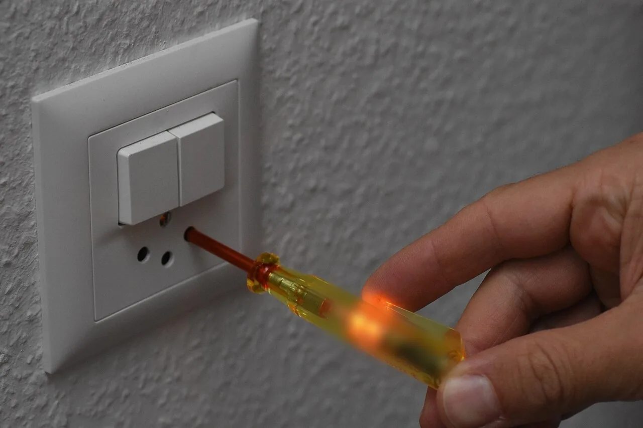
Figure 1. A neon test screwdriver glows when its tip touches the live contact of a socket. It is useful as a quick indication only; to prove a circuit dead before touching wires, use a two-pole voltage tester checked on a known live source. (Photo: Simon A. Eugster, Wikimedia Commons, CC BY-SA 4.0; brand text on the tester blurred)
Step 2: Remove the old switch and identify the wires
With the circuit proven dead, unscrew the old switch and pull it forward gently. Take a photo before you disconnect anything.
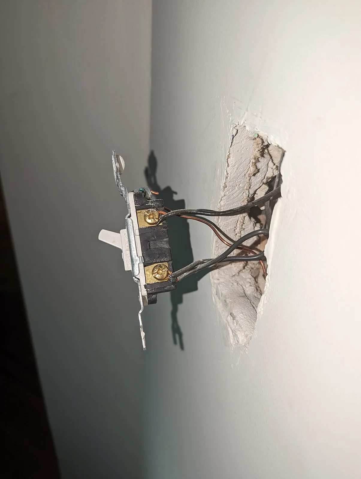
Figure 2. An old mechanical switch pulled out of the wall: two insulated wires on its screw terminals, with bare copper earth wires alongside. A mechanical switch needs no neutral, so many switch boxes do not have one. Photograph and label every wire before you disconnect anything. (Photo: Kurtkaiser, Wikimedia Commons, CC0)
What you usually find in a Vietnamese house:
One live feed (L) from the breaker, often looped across the gangs of a multi-gang switch with short jumpers, sometimes continuing to another switch.
One switched wire per gang, going up to each light.
Neutral wires, only in some boxes, usually joined in a connector at the back and not connected to the old switch, because a mechanical switch does not need them.
Earth wires in newer installations.
Do not rely on colour alone; older houses often use one colour for everything. Label each wire with tape as you identify it: "L feed", "L1 ceiling", "N".
How to confirm a neutral wire safely
A wire that "looks like" a neutral is not proof.
Trace it. Follow the conduit or cable to the junction box or lamp position and confirm it connects to the neutral of that same lighting circuit. This is the only check that proves "same circuit".
Continuity test, circuit isolated. A long test lead between the candidate wire and the neutral at the light fitting confirms it is a neutral conductor. But because all neutrals meet at the neutral bar in the board, continuity alone cannot tell you which circuit it belongs to. Also note that the switched wire may show continuity or a resistance reading to neutral through the lamp.
Be careful with live voltage checks too. With the switch open and a lamp in place, the switched wire can read a high voltage, often close to 230 V, against the live feed, because it is connected to neutral through the lamp. A 230 V reading between two wires does not prove either one is the neutral.
Two rules about neutral
Never use the earth wire as a neutral. Earth is a protective conductor, not a working one. Using it as a neutral can make metal parts live, cause RCD tripping and defeat the protection that earth provides.
Never borrow a neutral from a different circuit. The neutral must come from the same lighting circuit as the live. A borrowed neutral can trip RCDs, leave a conductor carrying current when someone thinks its circuit is off, and overload a conductor.
Step 3: Decide what to do if there is no neutral
With no neutral in the box, you have four choices. Explain them honestly to the client.
Run a neutral to the switch. If the wiring is in conduit, pull a new conductor of the correct size and colour from the same circuit's junction box or lamp position. Without conduit this means chasing and repairs, so quote it separately.
Fit a no-neutral smart switch. Check the minimum load per gang, the LED compatibility list and whether the maker supplies a bypass capacitor (sometimes called a compensator). It is fitted in parallel with the lamp at the light fitting, so the standby current flows through it rather than the LED driver. Fit only the device the manufacturer specifies, enclosed, with proper connectors.
Put the smart part where the neutral is. An in-wall relay module can sometimes go at the lamp or ceiling junction box, with the existing wall switch as its input. Follow its instructions for the switch input and keep it accessible, never buried in plaster.
Use smart bulbs and leave the wall switch on. Often the right answer for tenants.
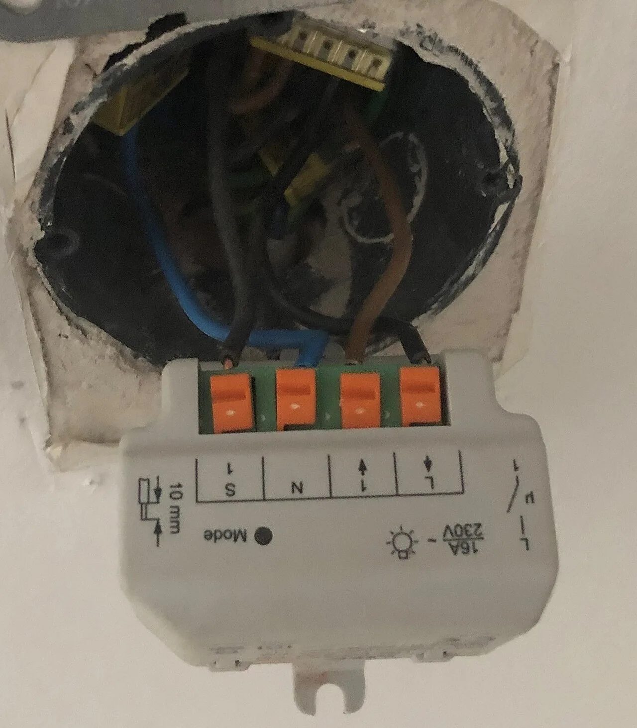
Figure 3. A flush-mounted smart relay module wired in a round wall box. Its terminals are labelled S1 (switch input), N, an output and L, and it is marked 230 V, 16 A. Modules like this need a neutral where they are fitted; always follow the terminal diagram of the exact product. (Photo: Simon Müller, Wikimedia Commons, CC BY-SA 4.0)
Step 4: Wire the smart switch
Again: power off and proven dead. Then follow the manufacturer's diagram exactly. A typical wiring for a smart switch with neutral is:
L feed → L terminal. If the old switch had a jumper looping the live to each gang, you usually no longer need it: most multi-gang smart switches feed every gang internally from one L terminal. Check the diagram.
Neutral → N terminal. Take the neutral from the bundle at the back of the box with a short tail and a suitable connector rated for the number and size of conductors. Do not twist and tape.
Each switched wire → L1, L2, L3. Match each output to the labels you made in Step 2. Leave unused outputs empty.
Looped feeds. If the live or neutral continues to another point, join the conductors in a proper connector and take a single tail to the switch terminal, unless the terminal is specified for two conductors.
Earth. If the switch or plate has an earth terminal, connect it. If not, keep the earth conductors joined in a connector at the back of the box, insulated and tidy. Do not cut them off.
Workmanship matters more with smart switches, which are fragile and full of electronics:
Strip only the length shown for the terminal, so no bare copper shows.
Tighten terminals firmly and tug each wire. A loose L or N causes resets and heat.
Fold the wires flat so the switch sits square. Do not pull it in with the fixing screws; that can crack a glass panel.
Expect a weaker Wi-Fi signal from a switch in a metal box.
For a no-neutral switch, the wiring is just L and L1–L3. If the manufacturer requires a bypass capacitor or minimum load, fit it now at the lamp, before you restore power.
Two-way (stair) circuits
A two-way circuit uses two switches linked by two traveller wires. Most Wi-Fi touch switches cannot simply replace one of them; connecting travellers to L1 and L2 does not make a smart switch two-way and can create a fault.
Instead, use a brand with paired multi-way control: one smart switch does the switching and a second unit at the other end sends commands by radio. That second unit still needs power (a neutral, or batteries for a wireless remote). Where the manufacturer allows, old travellers can be re-used, for example as a neutral, but only after identifying both ends, confirming the same circuit and re-labelling them. NAMBIN's guide on two-way switches explains traveller wiring.
Step 5: Restore power and pair the switch
Fit the plate, remove your lock-off and switch the breaker on.
Most switches blink when ready to pair. First press each key and check the correct light responds locally.
Pair it in the manufacturer's app on the client's own phone and account, not yours.
Follow the "add device" steps: phone on the same Wi-Fi network, location and Bluetooth permissions on, and a 2.4 GHz network if the product needs it.
Name each gang clearly ("Living room ceiling") so schedules and voice control work.
Figure 4. A smartphone next to smart home devices: a camera, a plug-in smart adapter and a smart LED bulb. Pair a smart switch in the manufacturer's app on the client's own phone and account, after checking that every gang works locally. (Photo: Jakub Zerdzicki, Pexels)
Step 6: Test the installation
Test everything before you leave:
Each gang on and off by touch, then by app.
With all gangs off, watch the lights in the dark for a minute. A faint glow or periodic flash means standby current is passing through the lamp.
Switch the breaker off and on. Many apps have a "power-on behaviour" setting (off, on or last state); most clients want "off", so lights do not come on by themselves after a night-time power cut.
After some minutes on, the plate may be slightly warm but never hot. Heat points to overload, a loose terminal or the wrong load type.
Check the RCD or RCBO does not trip when switching any gang.
Record the breaker number and switch model in your job notes.
Troubleshooting table
Symptom | Likely causes | What to check or do |
|---|---|---|
LED lights glow faintly or flash when "off" | No-neutral switch powering itself through the lamp; LED load below the switch's minimum | Fit the manufacturer's bypass capacitor at the lamp, increase the load if allowed, or change to a switch with neutral |
Switch keeps rebooting, clicking or going offline | Load too small for a no-neutral switch; loose L or N terminal; poor Wi-Fi signal; supply voltage problems | Re-check terminals with power off; check signal at the switch; check load requirements |
Switch will not pair | Phone on a 5 GHz network while the switch needs 2.4 GHz; wrong Wi-Fi password; phone permissions; weak signal in a metal box | Join the phone to the correct network, check permissions, follow the reset procedure in the manual |
Touch panel lights up but lamp never switches | Switched wire on the wrong terminal (L and L1 swapped); lamp or driver faulty | Isolate and check wiring against your labels; test the lamp separately |
RCD trips when the light is switched on | Neutral taken from a different circuit; neutral and earth mixed up; insulation fault in the lamp or cable | Isolate; confirm that neutral belongs to the same circuit; do not use earth as neutral; carry out insulation testing if competent |
Fan hums or runs at the wrong speed | Dimming-type or electronic (triac) output on a motor load; conflict with the fan's own speed regulator | Use only an output rated for motor loads, and follow the fan manufacturer's advice |
Switch plate gets hot | Load above the rating (especially many LED drivers); loose connection | Reduce load per gang or split circuits; re-terminate |
Safety checklist
Breaker locked or tagged off; tester checked before and after; all conductors proven dead.
Every wire labelled and photographed before disconnection.
Neutral confirmed as belonging to the same lighting circuit; no borrowed neutral; earth never used as neutral.
Product rated for 230 V / 50 Hz and for the actual load type and size on each gang.
No fan, pump or large appliance connected to an output not rated for it.
Terminals tight, no exposed copper, connectors rated for the conductors joined.
Earth conductors kept connected and insulated, not cut off.
Any bypass device fitted only as specified by the manufacturer, in an enclosure.
Local control, app control, power-on behaviour and RCD operation tested.
Client owns the app account; handover notes given.
Working with clients on smart switch jobs
Most complaints arrive days after you leave. Prevent them with a short handover:
Without internet, touch control should still work; remote control and schedules may stop.
After a power cut, the lights follow the power-on behaviour you set.
The client owns the account and the Wi-Fi password. Do not keep their login.
Record what you changed: new neutral, bypass device or relocated module.
If the client supplied the switch, agree that your warranty covers your workmanship, not the product.
When quoting, price each option from Step 3 separately instead of promising that "any smart switch will work".
Practical examples
Example 1: Two wires in an old house. An older townhouse has one live feed and one switched wire to a ceiling LED panel, no conduit, and the client does not want the wall cut. You fit a no-neutral switch from a brand that supplies a bypass capacitor. The panel glows faintly at night, so you fit the bypass device at the light fitting as the manual specifies. The glow stops, and you record the device in your job notes.
Example 2: A neutral that was not what it seemed. In a renovated apartment, a blue wire sits at the back of the switch box. You trace it and find it belongs to the kitchen socket circuit on a different RCBO, so you do not use it. You pull a new neutral through the lighting conduit from the ceiling junction box instead.
Example 3: Stair lights. For a stair with two-way switches, you fit a smart switch with neutral at the bottom and a paired battery wireless remote from the same brand at the top. The unused travellers are disconnected at both ends, insulated in connectors and labelled "spare", and the old top box gets a blank plate or the remote's mounting plate as the manual describes.
Frequently Asked Questions
Can I install a smart switch without a neutral wire?
Yes, with a switch designed for no-neutral use, if the lamp meets its minimum load and compatibility requirements. LED glow or flicker is possible; the manufacturer's bypass capacitor often solves it. A switch with neutral is generally more reliable.
Why do my LED lights flicker after installing a smart switch?
Usually a no-neutral switch drawing standby power through the LED driver. Other causes: load below the minimum, an incompatible dimming output, or a loose connection.
Can I use the earth wire as a neutral for a smart switch?
No. The earth conductor is for protection only. Using it to carry working current can make metal parts dangerous, cause RCD trips and is not acceptable wiring practice.
Can a smart switch control a ceiling fan?
Only if the output is rated for motor loads and the manufacturer permits it. Never use a dimming-type smart switch on a fan or combine it with the fan's own regulator unless the instructions allow it.
Why can't my phone find the switch during setup?
Many smart switches connect only to 2.4 GHz Wi-Fi. Check the network, password, phone permissions and that the switch is in pairing mode.
Can I replace a two-way stair switch with a smart switch?
Not by connecting the traveller wires to the smart switch outputs. Use the brand's paired multi-way system (smart switch plus a second linked unit or wireless remote) and follow its diagram.
Do smart switches use electricity when the lights are off?
Yes, a small standby amount for the electronics and radio, normally stated in the manual. That is why a no-neutral switch must pass a tiny current through the lamp.
Practice Exercises
Terminal mapping. Take the wiring diagram from any smart switch manual. Redraw it by hand, labelling L, N, L1–L3 and earth, and write next to each terminal which wire in a typical two-gang switch box would go there.
Identify the wires. On a training board with a lamp, a switch and a junction box, isolate the circuit, prove it dead, then use continuity testing to identify the live feed, the switched wire and the neutral. Write down which reading would fool you if you only measured voltage with the lamp in place.
No-neutral decision. For each of these, choose one of the four options in Step 3 and explain why: (a) tenant in a rented flat; (b) house with all wiring in conduit; (c) a single LED downlight on a no-neutral switch that flickers; (d) a switch box too shallow for any smart switch.
Fault-finding. A three-gang smart switch works, but the RCBO trips every time the third gang is switched on. List the checks you would make, in order, with the circuit isolated.
Load check. A client wants to put ten LED downlights on one gang of a smart switch. Using the ratings from a real product manual, decide whether that is within its LED rating and what you would do if it is not.