A client wants the gate light or signboard to come on by itself every evening and go off in the morning. A timer can do part of this, but sunset shifts through the year and a dark, rainy afternoon does not follow the clock. The simple answer is a photocell, also called a dusk-to-dawn sensor, light sensor switch or twilight switch: a small device that measures the daylight around it and switches the lights on when it gets dark and off when it gets light again.
A photocell is easy to wire and easy to install badly: too small for a row of LED floodlights and its contacts weld shut; mounted where the lamp shines on it and the light flashes all night. This guide covers choosing, wiring, mounting, adjusting, testing and troubleshooting one properly.
Scope of this guide. This article is for trainee and working residential electricians on single-phase 230 V / 50 Hz installations, as used in Vietnam. Photocells are installed on live mains circuits, often outdoors, at height and in damp conditions. Isolate the circuit and prove it dead before you touch any conductor, and follow current Vietnamese regulations and standards and the manufacturer's instructions for the exact device you are installing. Trainees should work under supervision. Numbers marked for reference are typical values or worked examples, not rules; always check the device's datasheet.
What a photocell switch does, and how it differs from a timer or a motion sensor
A photocell has a light-sensitive element behind a small window (a light-dependent resistor in older designs, usually a photodiode or phototransistor in newer ones), a small control circuit, and a relay that switches the line to the lamps. When the light drops below a set level the relay closes; when morning light rises above a slightly higher level it opens. This deliberate gap (hysteresis) stops the device chattering at dusk.
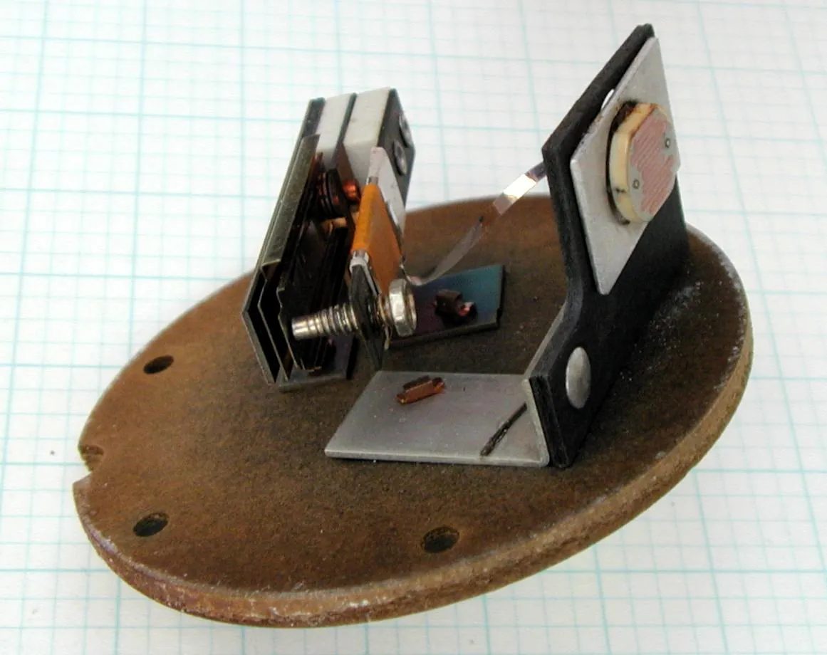
Figure 1. The inside of an older street-light photoelectric control with its cover removed: the round light-dependent resistor (the disc with the wavy track) is mounted on the upright bracket at the right, and the switching mechanism is on the left. Modern units are electronic, but the principle is the same: a light sensor drives a contact that switches the lamp. (Photo: MyName (Atlant), Wikimedia Commons, CC BY-SA 3.0)
It helps to be clear about what a photocell is not:
A timer switch follows the clock, not the actual light level.
A PIR motion sensor switches a light on for a short time when it detects movement; its light-level knob only stops it working in daylight. A photocell keeps the lights on all night, movement or not.
A photocell suits lights that should be on whenever it is dark: gate and porch lights, security lights, path lights and small signboards. To switch off at a set time of night, combine it with a timer (Step 6).
Common types of photocell you will meet
Wire-in (lead-wire) photocells
The most common type in houses is a small weatherproof body with a window and three flying leads, or three screw terminals inside a cover. The three connections are line in, neutral and load (switched line) out. The neutral is needed because the electronics and relay coil inside need a supply of their own. Lead colours are not standardised between brands: some use black, white and red; others brown, blue and red, or mark the terminals L, N and L' (or "Load"). Always follow the terminal diagram printed on the device or in its leaflet, never colours alone.
Twist-lock photocontrols
Street-light style photocontrols plug into a three-pin twist-lock socket on top of the luminaire or bracket arm. You will mostly see them on street lights and car parks.
DIN-rail twilight switches with a separate sensor
For larger jobs, the switching unit sits on the DIN rail in the distribution board and a small sensor head is mounted outside and connected with a low-voltage cable. The board unit usually has a display or dials for the light level and delay, and some models include a timer function.
Step 1: Choose the photocell and check its load rating
The most common reason a photocell fails early is that it was too small for the load. Read the rating label and datasheet carefully, because one device may carry several different ratings.
Contact rating is not the same as "watts of LED"
A label such as "10 A" or "2000 W" usually refers to a resistive load (a heater or an old incandescent lamp). LED lamps, LED floodlights and fluorescent fittings with electronic ballasts are very different loads. Each LED driver has input capacitors that draw a very large, very short inrush current at the instant of switch-on, many times higher than its normal running current. The relay contacts inside a photocell close into that surge every evening. If the surge is too large, the contacts arc, pit and can eventually weld closed, so the lights stay on day and night.
Good manufacturers give a separate rating for LED, CFL or "electronic ballast" loads, often much lower than the resistive rating, or a maximum number of drivers. Use that figure. If the datasheet gives no LED rating at all, treat the device with caution: many electricians then leave a large margin and switch only a fraction of the resistive rating (for reference, a rule of thumb, not a standard), or use a contactor as described in Step 6.
Work out the load current
Add up the power of all the fittings the photocell will switch and convert it to current:
I = P ÷ (U × power factor)
Example: eight LED floodlights, each 50 W with a power factor of about 0.9 (check the fitting's label), on 230 V: I = 400 ÷ (230 × 0.9) ≈ 1.9 A. The running current is small, but eight drivers switched together give a combined inrush a small photocell may not tolerate. Compare the total wattage and the number of drivers with the photocell's LED rating, not with its resistive rating.
Other things to check before buying
Voltage and frequency: the device must be rated for 220–240 V, 50 Hz. Some imported photocells are 120 V only.
IP rating: for outdoor use choose a device made for outdoor mounting, with an IP rating that suits the location (for reference, IP44 is often considered a minimum for sheltered outdoor positions and IP65 for exposed ones; follow the maker's guidance).
Adjustment: prefer a model with an adjustable light-level knob.
Delay: most good photocells have a built-in delay so a car headlight, a lightning flash or a passing cloud does not switch them.
Fail mode: some photocontrols are designed to "fail on" (lights stay on if the sensor fails), others "fail off". For a security light, fail-on is usually preferable.
Reference table: matching the photocell to the load
The table below is for reference only. Ratings vary widely between models; always check the manufacturer's data for the exact photocell, contactor and lamps.
Load being switched | What to check on the photocell datasheet | Typical approach (for reference) |
|---|---|---|
One or two small LED lamps (porch light, house number) | LED / electronic ballast rating, or maximum number of LED lamps | A good-quality wire-in photocell switching the lamps directly is usually fine |
Several LED floodlights or a long row of garden lights | LED rating in watts or number of drivers; inrush (peak current) limit if given | Stay well within the LED rating; if the total is near or above it, use a contactor |
Incandescent or halogen lamps (resistive) | Resistive or "incandescent/tungsten" rating | Can usually use the resistive rating, but leave some margin |
Fluorescent fittings with electronic ballasts, CFLs | "Electronic ballast" or CFL rating | Treat like LED drivers: high inrush, use the lower rating |
Discharge lamps (metal halide, sodium) with magnetic ballasts | Inductive rating, often given in VA | Usually better switched by a contactor sized for lighting loads |
Large signboards, car parks, several circuits | Whether the photocell may switch a contactor coil (inductive) | Photocell switches only the contactor coil; the contactor switches the lamps |
Step 2: Isolate the circuit safely
Treat the existing lighting circuit as live until proved dead:
Identify the MCB or RCBO that feeds the lighting circuit. Do not rely on the wall switch: the neutral and sometimes a permanent line can still be live in the outdoor box.
Switch the breaker off, lock it off if you can and put a tag on it so nobody switches it back on.
Prove dead at the point of work with an approved two-pole voltage tester: check the tester on a known live source, test between L–N, L–E and N–E, then check the tester again. A non-contact voltage pen alone is not enough to prove a circuit dead.
Outdoors on a ladder: firm ground, someone footing it, no work in rain.
Outdoor lighting circuits should be protected by a residual current device (RCD or RCBO, typically 30 mA). If the circuit has no RCD protection, tell the client and recommend adding it as part of the job.
Step 3: Wire the photocell (L, N and load)
The photocell goes in the line conductor between the supply and the lamps, exactly where a switch would go, with an extra neutral connection for its electronics.
Basic wiring for a three-wire photocell
Supply line (L) from the breaker → photocell Line in terminal.
Supply neutral (N) → photocell N terminal and the neutral of every lamp (joined in a suitable connector).
Photocell Load out (switched line) → the line terminal of every lamp.
Protective earth (PE) → the earth terminal of every metal (Class I) fitting. The photocell itself usually has no earth terminal; if it does, connect it.
Never put the photocell in the neutral. If the neutral is switched, the lamp holders and drivers stay live at line voltage even when the light is off, which is a shock risk for the next person who changes a lamp.
Making good connections
Make all joints in a proper junction box or in the photocell's own terminal compartment, using screw terminals or lever connectors rated for the conductor size.
Fit ferrules on fine-stranded flying leads if the terminals need them, and tighten screws to the torque in the instructions.
Use cable rated for outdoor use and sunlight where it is exposed, or run it in UV-resistant conduit.
Keeping a manual switch
Clients often want to keep the existing wall switch. There are two common arrangements:
Switch before the photocell (in series): the wall switch feeds the photocell's line-in. Switch ON = automatic dusk-to-dawn; switch OFF = lights off completely, for example while travelling. The photocell restarts, with its delay, each time it is switched back on.
Bypass switch (in parallel with the photocell output): a switch connected from the supply line to the load line lets you force the lights on in daylight, for example for maintenance. Label it clearly: if it is left on, the lights burn all day and it looks like a faulty photocell. Check the instructions allow a parallel switch, as some electronic (non-relay) photocells do not.
On larger systems, an Auto – Off – On selector switch controlling a contactor coil does both jobs.
Step 4: Choose the mounting position and orientation
Where you mount the sensor matters as much as how you wire it. The photocell must see the natural light of the sky, and as little artificial light as possible.
Rules for a good position
Face it away from the lamps it controls. If the lamp's own light reaches the sensor window, the photocell switches the lamp on, sees the light, switches it off, sees darkness, switches it on again, all night. This is called light feedback. Reflections count too: a white wall, glass or a shiny gate lit by the lamp can reflect enough light back.
Keep it away from other artificial light: street lights, a neighbour's floodlight, a signboard, car headlights sweeping across a gateway.
Avoid deep shade under a deep roof, a balcony or a dense tree. In shade the sensor thinks dusk comes early, especially on cloudy afternoons, and the lights come on too soon.
Direct sun: follow the maker's instructions on orientation. Many recommend that the window does not face straight into the sun; for devices sold in the northern hemisphere a north-facing window is often suggested. Vietnam lies in the tropics, where the sun can pass to the north of overhead in summer, so use the maker's advice and the actual shading of the site.
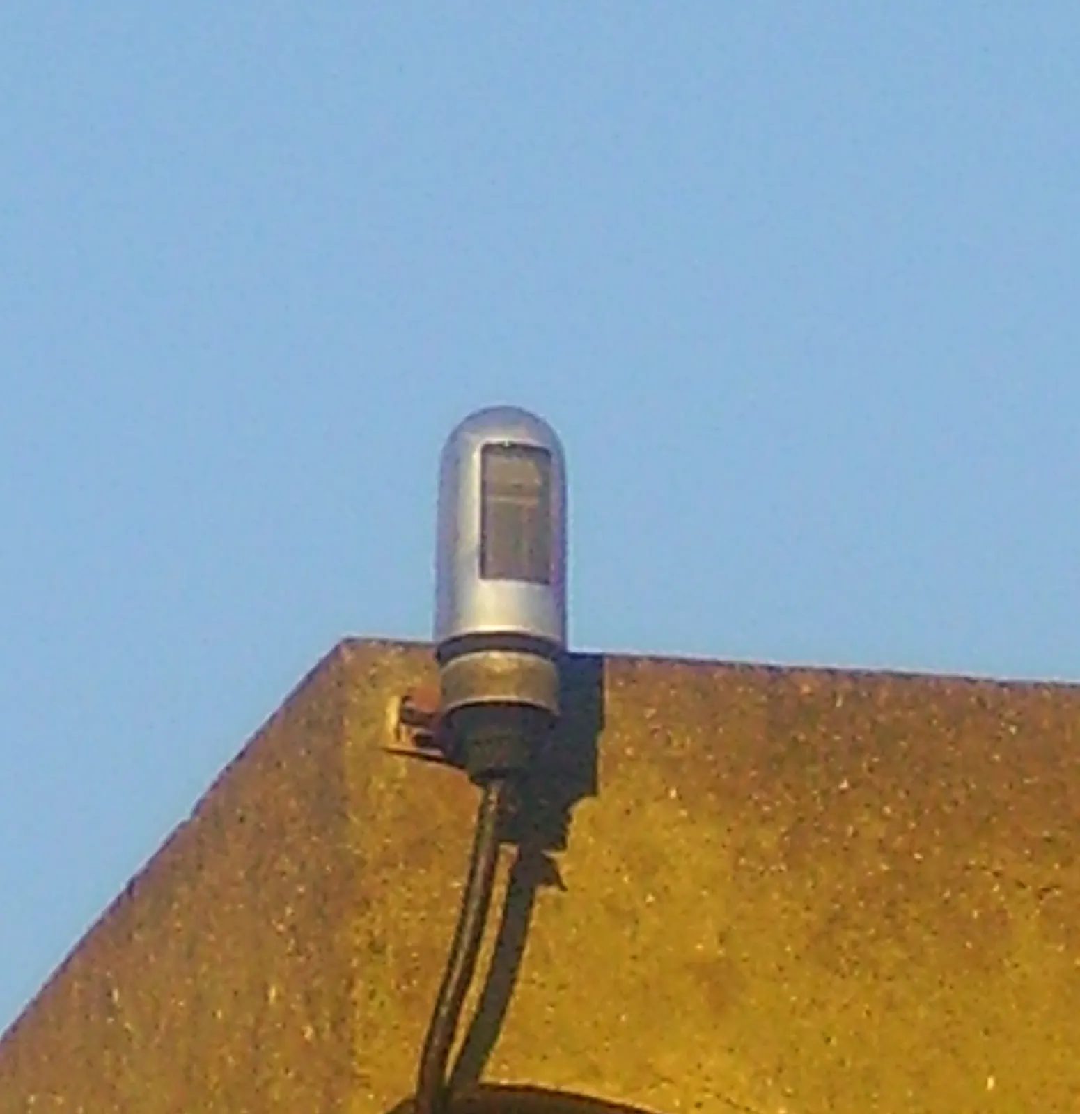
Figure 2. An outdoor twilight switch sensor mounted on a bracket at the corner of a building, with its window facing out to open sky and the cable entering from underneath. The cable runs down the wall, so rain cannot run along it into the device. (Photo: Serpicozaure, Wikimedia Commons, CC BY-SA 3.0)
Weatherproofing
Mount the device the right way up, normally with the cable entry facing downwards, as shown in its instructions. Never drill the top of the enclosure.
Form a drip loop: let the cable dip below the entry point before it rises into the device, so water running along the cable drips off at the bottom of the loop instead of following it inside.
Use the supplied gland or grommet and make sure it grips the cable sheath. Seal unused entries with the correct blanking plugs.
Never paint or put sealant over the sensor window.
Step 5: Adjust the light level and delay
Many photocells have a small knob or screw marked with a sun and a moon symbol, or a scale in lux. Turning towards the sun makes the lights come on earlier, at a brighter light level; turning towards the moon makes them come on later, when it is darker. The adjustment range and the delay vary by model, so check the datasheet.
The most reliable way to set it is on site at dusk:
Start with the knob at the darker (moon) end, or at the factory setting.
At the moment of evening when the client wants the lights on, turn the knob slowly towards the sun until the lights switch on.
Remember the built-in delay. After each small turn, wait for longer than the delay time before turning further, or you will overshoot.
Any adjustment while the device is energised must be done through the adjustment opening provided by the manufacturer, with the cover closed, using an insulated screwdriver. If the knob is inside the terminal compartment, isolate, adjust a little, close up and re-energise for each step.
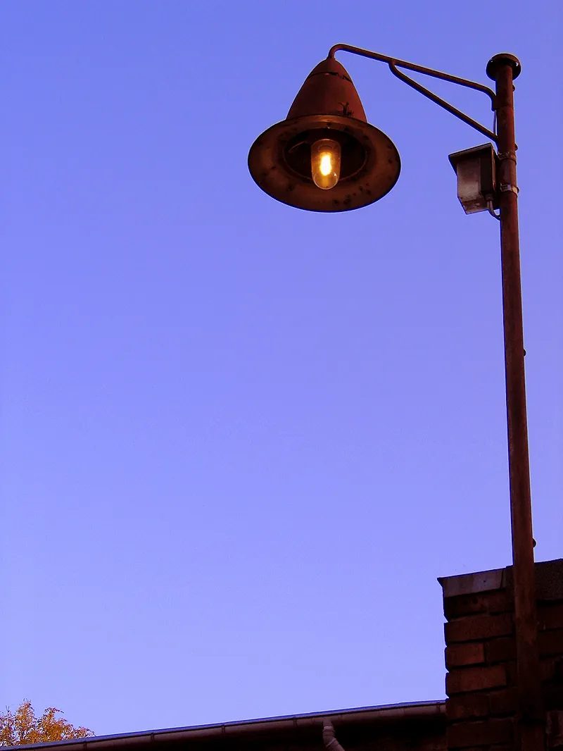
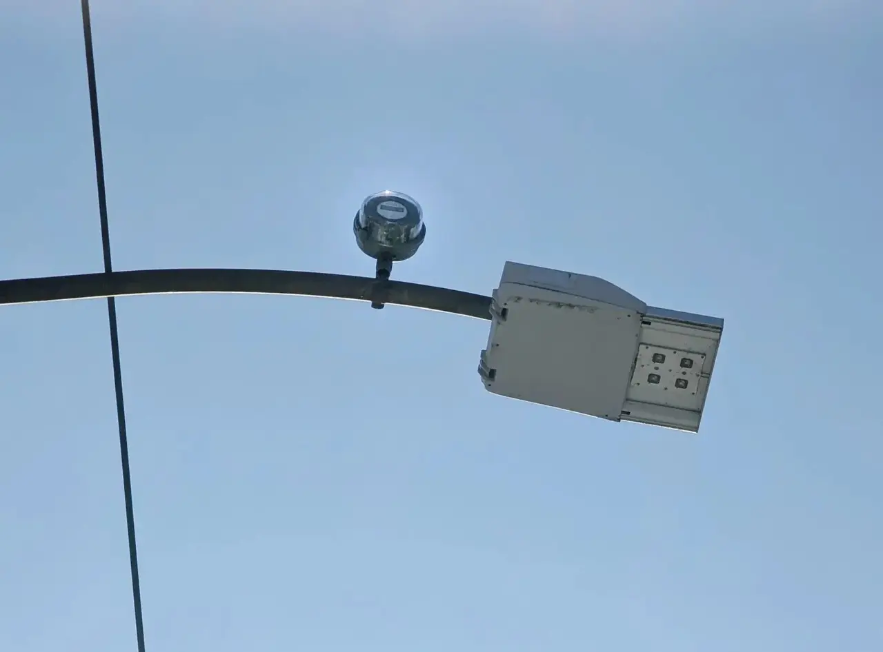
Figure 3. An old courtyard lamp already switched on at dusk by a twilight switch, while the sky is still blue. A small box is mounted on the pole just below the lamp arm. Agree with the client how dark it should be before the lights come on. (Photo: Bernd Schwabe in Hannover, Wikimedia Commons, CC BY-SA 3.0)
Step 6: Combine the photocell with a timer or a contactor
Photocell plus timer: on at dusk, off at midnight
Many clients do not need the signboard or garden lights on until sunrise. The usual solution is to connect the photocell output and a timer contact in series, so the lights are on only when it is dark and the timer is in its "on" period.
Power the timer from the permanent line and neutral so its clock runs all day.
Feed the photocell's load output through the timer's switching contact to the lamps or to a contactor coil.
Set the timer to be ON from late afternoon (earlier than the earliest sunset of the year) until the switch-off time the client wants, for example midnight. The photocell decides the switch-on moment; the timer decides the switch-off.
Check the timer's contact rating as carefully as the photocell's. (An astronomical timer, which calculates sunset from date and location, is a sensor-free alternative.)
Using a contactor for large loads
When the lighting load is larger than the photocell's LED rating, or the client has several lighting circuits, let the photocell switch a contactor coil and the contactor switch the lamps:
Photocell (and timer, if used) output → contactor coil terminal A1; coil terminal A2 → neutral. Use a contactor with a 230 V AC coil.
Protect the control circuit with its own small MCB, as recommended by the maker.
The lamp circuits pass through the contactor's main contacts, each protected by its own MCB or RCBO.
Choose the contactor from the manufacturer's lighting-load tables (they give the number of LED drivers or the lamp wattage per pole), not from its headline current alone.
Check that the photocell is allowed to switch an inductive load such as a contactor coil; most can, but some datasheets limit it.
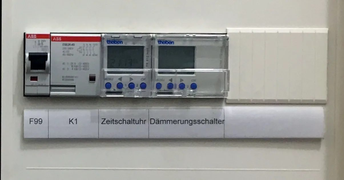
Figure 4. Outdoor-lighting control in a shop's distribution board, labelled in German: F99 is the protective circuit breaker, K1 the installation contactor that switches the lights, "Zeitschaltuhr" a digital time switch and "Dämmerungsschalter" a twilight (photocell) switch unit, which works with a light sensor mounted outside. (Photo: Pittigrilli, Wikimedia Commons, CC0)
Step 7: Test the installation
Before you pack up, test the system in daylight. The easiest method is to cover the sensor window to simulate darkness.
Check all covers are closed and the enclosure is sealed before re-energising. Switch the breaker on.
Some photocells switch the lights on briefly at power-up, then off after their delay. This is normal for some models; read the leaflet.
In daylight, the lights should be off once the delay has passed.
Cover the sensor window completely with opaque tape, a black cap or a thick dark cloth. Do not cover it with your hand while touching the device. After the delay the lights should come on.
Uncover the sensor. After the delay the lights should go off again.
If you fitted a timer or bypass switch, test each mode: Auto, forced On, Off, and the timer's switch-off.
Check (or ask the client to check) the first real dusk for flashing caused by light feedback.
Troubleshooting: lights stay on, stay off, or cycle at dusk
The lights stay on all day
Bypass switch left on, or the lamp line was connected to the supply line by mistake instead of to the photocell's load output. Check the wiring first.
Sensor in shade or covered: tape left on after testing, a dirty, painted or faded window, a new awning or a grown tree.
Threshold set too bright (knob turned fully to the sun end).
Welded relay contacts, common when a photocell switches too many LED drivers. If the lights stay on in daylight with the wiring correct, the bypass off and the window clean, suspect the contacts. Replace the photocell and fix the cause: reduce the load or add a contactor.
Fail-on design: some photocontrols deliberately fail with the lights on.
The lights never come on
No supply: MCB or RCD tripped, wall switch off, or neutral not connected to the photocell (without a neutral, three-wire electronic photocells cannot work).
Another light source reaches the sensor at night: a street light, a neighbour's light, a signboard, or the client's own other lighting.
Threshold set too dark, so it only switches on in near-total darkness.
Failed lamps or drivers: check them on a known-good supply.
Failed photocell: if supply and neutral are present at the device, the window is covered, the delay has passed and there is no output at the load terminal, the photocell is faulty.
The lights flash on and off at dusk (cycling)
Light feedback is by far the most common cause: the lamp lights the sensor, the sensor turns the lamp off, and the cycle repeats. Turn the sensor so its window faces away from the lamp, move it, or fit a shade made for that model. Remember reflections from walls and glass.
Little hysteresis or delay on a cheap device: move the sensor or choose a better model.
LEDs glowing or flickering when "off": some electronic photocells pass a tiny leakage current to the load, which can make very low-power LED lamps glow. This is a compatibility issue between the sensor and the lamp; a different photocell, a higher load or a contactor usually solves it.
Safety checklist
☐ Circuit identified, isolated, locked off, tagged and proved dead with a two-pole tester
☐ Ladder stable and footed; no work in rain or on wet surfaces
☐ Photocell rated for 220–240 V 50 Hz and for the actual load type (LED rating checked, not just the resistive rating)
☐ Contactor used where the load exceeds the photocell's LED rating
☐ Photocell in the line conductor; neutral never switched
☐ All metal fittings earthed; outdoor circuit protected by an RCD
☐ All joints in suitable boxes with proper connectors; no taped joints outdoors
☐ IP rating suitable for the location; cable entry downwards; drip loop formed; glands tight and unused entries sealed
☐ Sensor faces away from the lamps it controls and from other artificial light
☐ Any adjustment done with covers closed or the circuit isolated
☐ Cover test passed: off in daylight, on when covered, off again when uncovered
☐ Bypass or selector switch labelled; client shown how the system works
Frequently Asked Questions
Can I use a photocell with LED lights?
Yes, and it is the most common combination today. Choose a photocell that states an LED or electronic ballast rating and keep the total load within it. For many floodlights, use a contactor so the photocell only switches the contactor coil.
Why does my photocell need a neutral wire?
The electronics and the relay coil inside need their own supply. In a three-wire photocell, line and neutral power the device, and the third wire is the switched output to the lamps. Without the neutral, it cannot operate.
How do I make the lights turn off at midnight instead of at dawn?
Put a timer contact in series with the photocell output, as described in Step 6, and set the timer to switch off at midnight. The photocell turns the lights on at dusk and the timer turns them off.
Why do the lights come on during heavy afternoon rain?
The sensor responds to light, not time, and a dark storm can drop the light below the setting. If it bothers the client, set the threshold slightly darker, but not so dark that the lights come on late on normal evenings.
Practice Exercises
Load calculation. A client has six 30 W LED wall lanterns (power factor 0.9) on one circuit. Calculate the running current at 230 V. (Answer: I = 180 ÷ (230 × 0.9) ≈ 0.87 A.) Then look up the LED rating of a photocell sold in your area and decide whether it can switch them directly.
Wiring diagram. Draw the wiring for a three-wire photocell controlling two Class I lamps, showing L, N, load and PE, plus a bypass switch. Mark which conductors are live when the photocell is off.
Photocell plus timer. Draw a circuit where a photocell and a timer contact in series control a contactor coil, and the contactor switches three garden lighting circuits, each with its own MCB.
Fault finding. Your trainer sets up a training board where the light flashes on and off every few seconds at dusk. List the possible causes in order of likelihood, then find and fix the fault.
Size the photocell for the real load, wire it in the line with its own neutral, mount it where it sees the sky and not its own lamp, keep water out, and test it by covering the sensor before you leave. Then the client's lights will look after themselves, with no call-back.