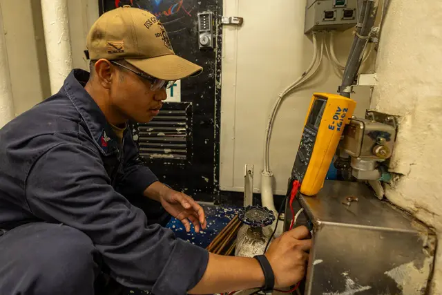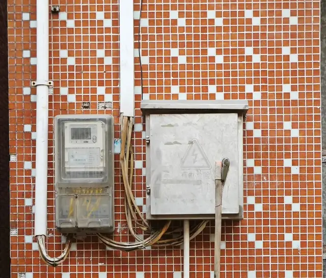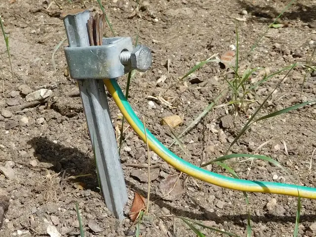
Wiring a residual current device (RCD) correctly means: take the phase (L) and neutral (N) from the supply into the two top terminals, take exactly the L–N pair of the protected circuit out of the two bottom terminals, run the protective earth (PE) straight to the appliance, and then press the TEST button to make sure it trips. Most cases of "it trips the moment I switch it on" or "there is an RCD but I still got a shock" come from a wrongly wired neutral, the wrong rating, or never pressing TEST.
In Vietnam, tradespeople and homeowners usually call this device an "aptomat chong giat" — literally an "anti-shock breaker". This lesson covers one device for one circuit (water heater, bathroom, washing machine, pump). Laying out a whole consumer unit and installing an earth rod are covered in the lesson Installing a home consumer unit: MCB and RCBO layout and safe earthing.
By the end of this lesson, you will be able to:
- Explain how an RCD "counts" current and how an RCBO differs from an RCCB.
- Choose the correct 30 mA sensitivity, rated current and type AC/A for a water heater, bathroom, washing machine and pump.
- Read and draw a wiring diagram for an RCD on one circuit, with L–N in and out correctly and PE not passing through the device.
- Recognise and fix four neutral wiring faults that make an RCD trip as soon as there is load.
- Test an RCD with its TEST button and with a trip-time tester, and record a handover report for the homeowner.
Want supervised practice? Wiring, measuring and commissioning residual current devices is practised and graded in the Residential Electrician Level 2 – Electrician course (Protective Devices module).
What is an RCD and how does it work?
The "anti-shock breaker" is a residual current device (RCD). In shops you will see three names: RCCB, RCBO and the older name ELCB. They all share one core component: a sensor that compares outgoing and returning current.
Principle: comparing current out on L with current back on N
Both the L and N conductors pass through a ring-shaped (toroidal) iron core. Normally the current going out on L equals the current returning on N, so their magnetic fields cancel. When part of the current escapes to earth — through a leaky water-heater casing, through water, through a person — the current returning on N is smaller than the current on L. That difference is the residual (leakage) current, IΔ. When IΔ reaches the threshold, an internal relay releases the mechanism and the device disconnects both L and N (see Figure 1).
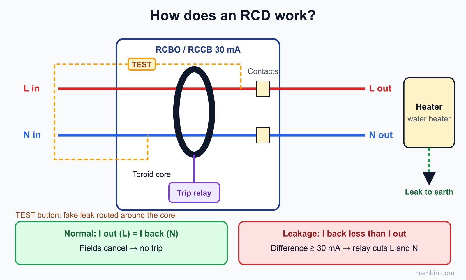
The key point: the device does not care whether the load is large or small. A water heater drawing 11 A runs happily without tripping it, but 30 mA going astray is enough. And it only sees the current in the conductors that pass through its core — the root of every neutral wiring fault later in this lesson.
Why 30 mA is used to protect people
At 50 Hz, around 10 mA through the body can already cause muscle contraction so you cannot let go; a few tens of mA for long enough can disturb the heart rhythm. A standard 30 mA device must trip within 300 ms at its rated residual current and within 40 ms at five times that current (per IEC 61008/61009). These limits greatly reduce the risk of death from direct contact — but they do not mean a person touching a live part feels nothing.
How do RCBO and RCCB differ?
The main difference: an RCCB only protects against leakage; an RCBO is "MCB + leakage protection" in one body.
| Criterion | RCCB | RCBO |
|---|---|---|
| Protection | Leakage only | Leakage + overload + short circuit |
| Product standard | IEC 61008 | IEC 61009 |
| Markings on the front (example) | 2P 40A 30mA | 1P+N C16 30mA |
| Needs an MCB alongside? | Yes — an MCB before or after to protect the cable | No, it protects the circuit cable itself |
| When one circuit leaks | The whole group behind it loses power | Only that circuit loses power |
| Sensible use | Shared protection for a group of 2–4 socket circuits | Dedicated circuits: water heater, washer, pump, bathroom |
Shops often call everything "ELCB"; when buying, read the label: a curve letter (B, C) before the amp rating, as in "C16", means RCBO; just an amp rating such as "40A" means RCCB.
Choosing a 30 mA RCD for bathrooms and water heaters
Four parameters must be chosen: residual current rating, rated current, type AC/A and number of poles. Get one wrong and the device either fails to protect people or trips constantly.
Residual current rating: bathrooms and water heaters are always 30 mA
Bathroom, water heater, washing machine, pump and socket circuits should have 30 mA residual current protection — which is also the IEC 60364 requirement for bathrooms. Do not choose 10 mA for a water heater: older elements have a small natural leakage and will cause nuisance tripping, so the owner looks for a way to remove the device. Do not choose 100 mA or 300 mA: those are fire-protection ratings, far too high to protect people.
Rated current and cable size
The overcurrent part of an RCBO protects the cable, so choose by cable size and load current: I = P ÷ 220. The detailed method is in the roadmap step "Reading diagrams & household load calculation". The table below covers the most common circuits:
| Circuit | Power | Current ≈ P ÷ 220 | Copper cable | Suggested device |
|---|---|---|---|---|
| 30-litre storage water heater | 2500 W | 11.4 A | 2.5 mm² | RCBO 1P+N C16 30mA |
| Instant water heater | 4500 W | 20.5 A | 4 mm² | RCBO 1P+N C25 30mA |
| Washing machine | 2000 W | 9.1 A | 2.5 mm² | RCBO 1P+N C16 30mA type A |
| Booster pump | 750 W | ≈ 4.3 A (power factor ≈ 0.8) | 2.5 mm² | RCBO 1P+N C16 30mA |
| Group of 3 socket circuits on one floor | 3 × 2000 W | 9.1 A per circuit | 2.5 mm² | RCCB 2P 40A 30mA + 3 MCB C16 |
For instant water heaters, always check the manufacturer's installation instructions — some models require larger cable and breakers. For long runs or many cables in one conduit, a qualified electrician recalculates the cable size with installation correction factors before choosing the breaker.
Type AC or type A?
Type AC detects alternating leakage current; type A also detects pulsating DC leakage from electronics and inverters. Water heaters and pumps can usually use AC; washing machines, inverter air conditioners and induction hobs should use type A as the manufacturer recommends. If in doubt, choose A.
RCD wiring diagram with correct L–N
The rule behind every RCD diagram: every current-carrying conductor of the circuit (L and N) must pass through the device; PE must not. Supply in at the top terminals, load out at the bottom, following the markings on the body.
RCBO 1P+N diagram for a water heater circuit
Figure 2 shows the standard wiring for a dedicated circuit. The RCBO takes phase from the busbar after the main MCB and neutral from the board's N bar into its two top terminals. The two bottom terminals send the red–blue pair to the water heater. The green/yellow wire runs from the PE bar straight to the heater casing.
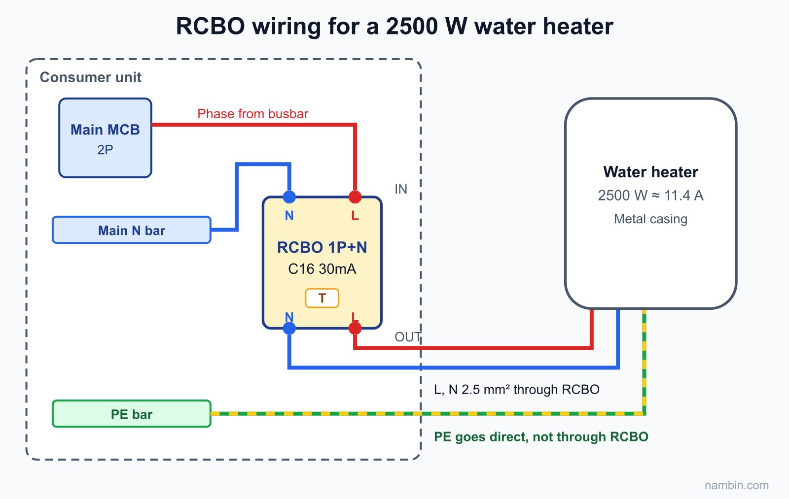
On a 1P+N RCBO, the neutral terminal has an N printed right next to it (many models put N on the left). Correct wiring: the red wire into the terminal marked 1 (or L), the blue wire into N; on the output side the corresponding terminals are 2 and N.
RCCB diagram protecting a group of MCBs
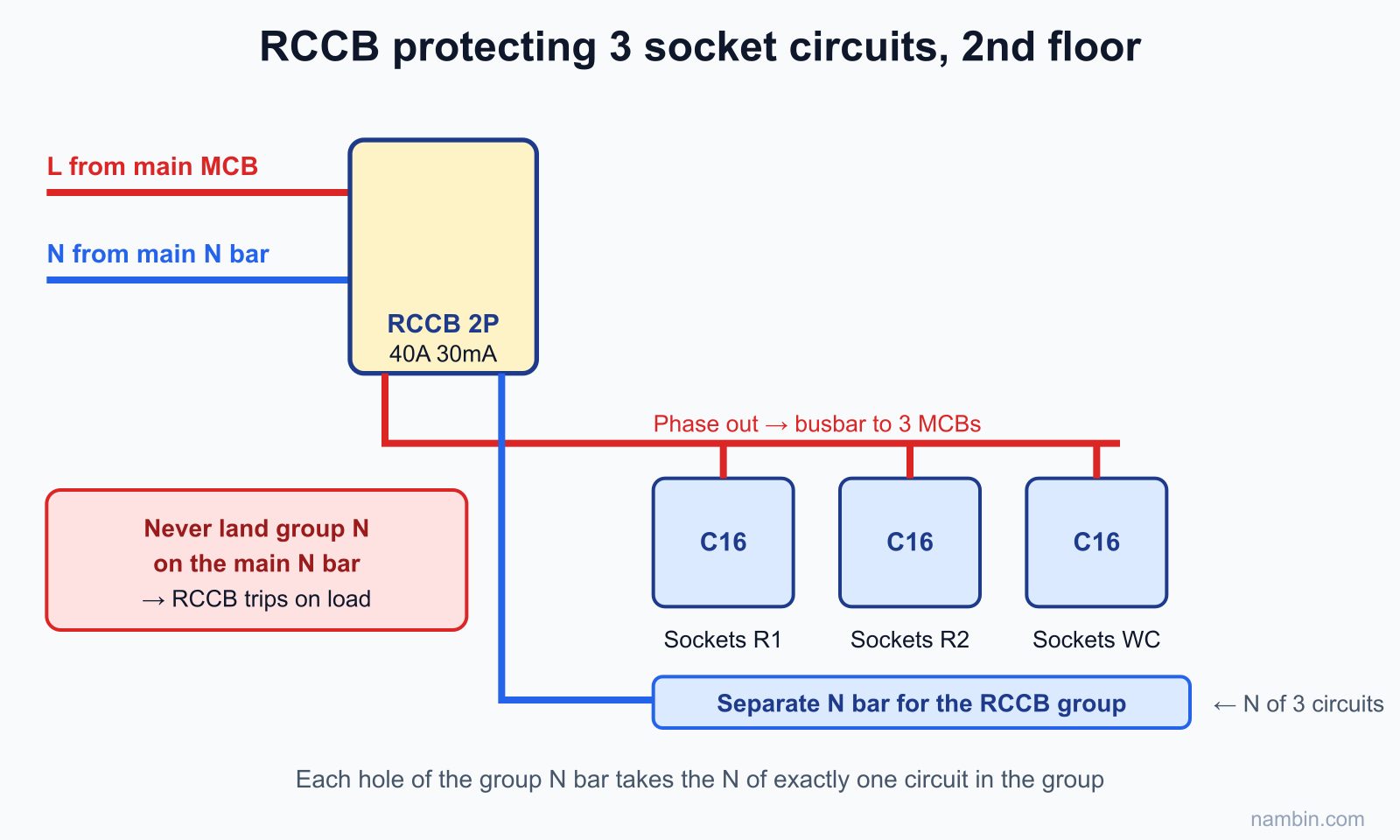
When using an RCCB for a floor's socket circuits, the RCCB's phase output feeds the branch MCBs, while its neutral output must go to a separate N bar for the group, completely isolated from the board's main N bar (see Figure 3). The neutrals of the circuits in the group may only land on this separate bar. (In Vietnamese tube houses, a narrow multi-storey terraced home, each floor often gets its own group.)
Why must PE not pass through the device?
PE is the path for leakage current to earth. If PE passes through the core (for example by landing PE on one pole of a 4-pole RCCB), leakage that goes out on L and returns on PE stays inside the core — the device sees no difference and does not trip.
Supply on top, load below — per the label
Devices are usually marked 1, 3 (or LINE) on the supply side and 2, 4 (or LOAD) on the load side. RCBOs with internal electronics often require the supply on the side marked on the label — follow the label and you will not go wrong.
How to wire an RCD step by step
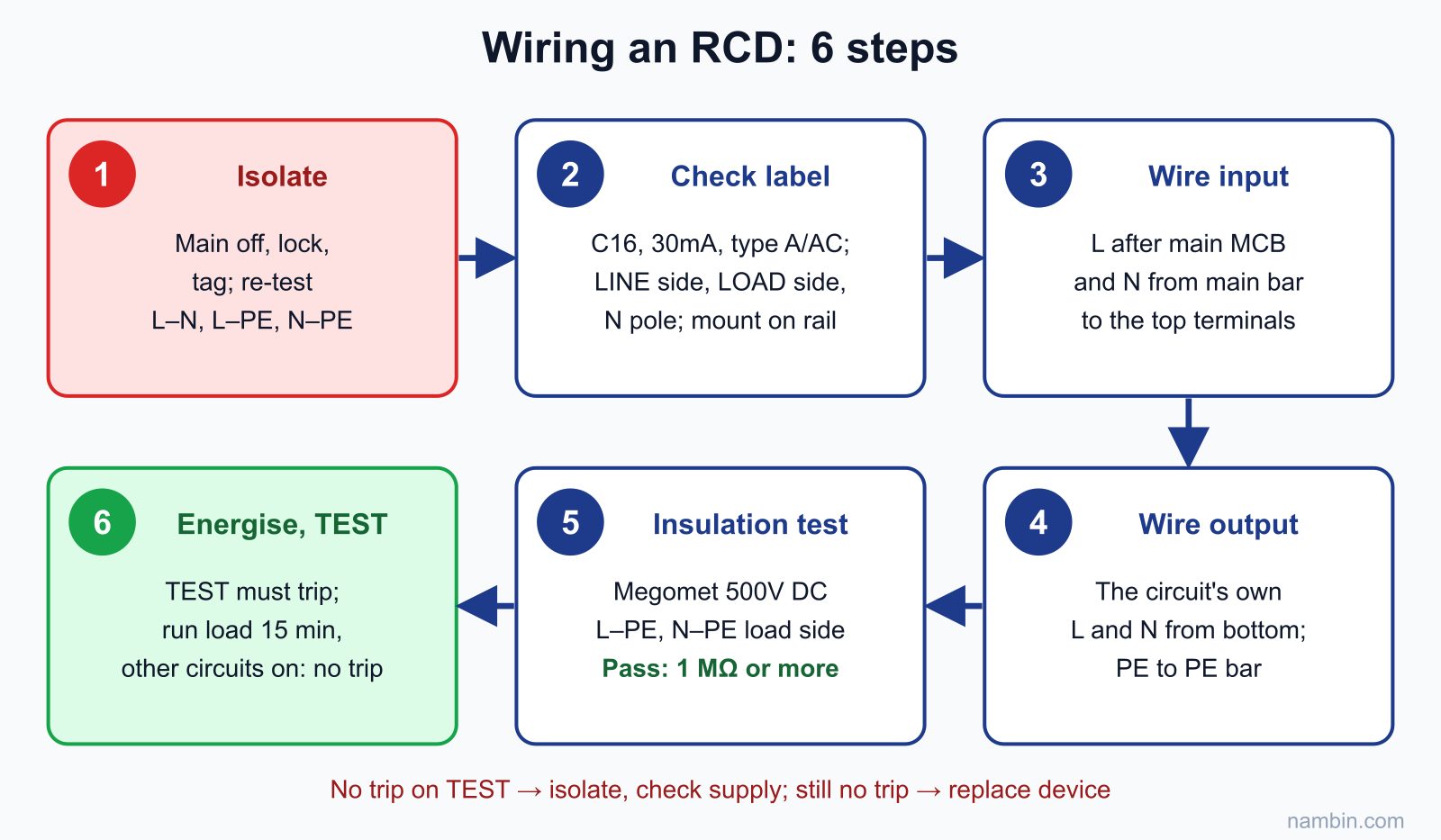
The procedure below applies to a new installation or to replacing a plain MCB with an RCBO in an existing board. Figure 4 summarises the six main steps.
Tools and materials
An RCBO/RCCB with the right ratings, pin ferrules for stranded wire, insulated screwdrivers, wire strippers and crimpers, voltage tester pen, multimeter, 500 V insulation resistance tester (megger), an RCD tester if available, a lock and a "Work in progress — do not switch on" tag.
Wiring steps
- Isolate and re-test: switch off the main breaker, lock it and tag it. Measure L–N, L–PE and N–PE at both input and output of the mounting position; prove the tester on a known live source before and after measuring.
- Check the label, mount on the rail: re-read C16, 30mA, type A/AC; identify the supply side, load side and N pole.
- Wire the supply: phase from after the main MCB into the top L terminal, neutral from the main N bar into the top N terminal. Strip just enough wire, with no exposed copper.
- Wire the circuit output: red into the bottom L terminal, the blue wire of this very circuit into the bottom N terminal — do a continuity check from the N wire at the heater back to the board to be sure. Land the PE wire on the PE bar.
- Tighten and insulation test: torque correctly and tug each wire. Test L–PE and N–PE on the load side at 500 V DC; you need 1 MΩ or more. Leave the RCBO OFF while testing so its internal electronics are not damaged.
- Energise and test: switch on the main and then the RCBO, press TEST: it must trip immediately. Reset, run the load for 15 minutes and switch on other circuits — it must not trip.
Isolation safety: Never wire or remove an RCD with the board live, even "just to change one wire". Upstream of the main breaker and the meter is always live from the grid — that belongs to the electricity utility and you must not touch it. Having an RCD does not mean live work is allowed: current flowing from L to N through your hands is not leakage, and the device will not trip. If you are not trained and supervised, do not do this work yourself.
Shared neutral faults that make an RCD trip
A newly installed RCD that "trips the moment it is switched on" or "trips when the bathroom light is turned on" is usually not faulty; the neutral is taking the wrong path. Any current that leaves through the device's L but returns another way (or the reverse) is counted as leakage.
Fault 1: borrowing another circuit's neutral
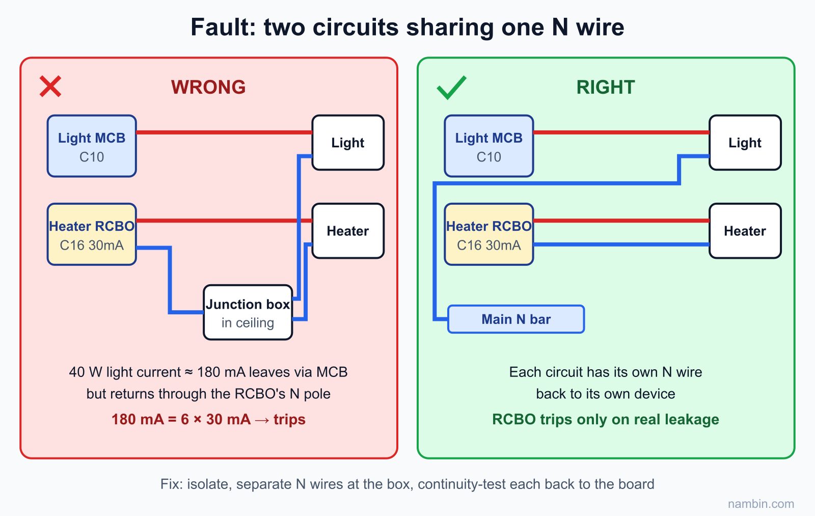
Symptom: the water-heater RCBO trips when the bathroom light or extractor fan is switched on, even with the heater off. Cause: in a ceiling junction box, a previous installer joined the lighting circuit's N (fed through a plain MCB) to the heater circuit's N (fed through the RCBO). Lighting current leaves through the MCB but returns through the RCBO's N pole — the RCBO sees more current coming back than going out. A 40 W light and fan draw 40 ÷ 220 ≈ 0.18 A = 180 mA, six times the 30 mA threshold, so it trips instantly (see Figure 5). Fix: isolate, separate the two N wires in the box, use continuity tests to find which N wire returns to the board on which circuit, and run a separate neutral for each circuit.
Fault 2: N connected to PE downstream of the device
Symptom: it can be switched on, but trips as soon as there is load; the larger the load, the faster it trips. Cause: the N wire shares the earth terminal at a socket (a "temporary" bodge when the house has no earth rod) or a crushed sheath touches a metal box connected to PE; part of the return current flows on PE, outside the core. With an 11.4 A heater, just 1% of the current on the PE path is 114 mA, almost four times the threshold. Fix: isolate, disconnect the load and measure N–PE resistance downstream of the RCBO: it must be very high (1 MΩ or more on a megger). If low, find and separate the contact point.
Faults 3 and 4: N to the shared bar, crossed or reversed
If the circuit's N lands on the main N bar instead of the RCBO's own N terminal, it trips as soon as there is load; if two adjacent RCBOs have their neutrals crossed, switching on a load on one circuit trips the other. How to find these two faults is in the lesson Breaker keeps tripping: a 6-step procedure to find the real cause. Wiring phase into the N terminal does not cause tripping, but the overcurrent protection sits on the wrong conductor and the next electrician can easily mistake the phase. After energising, check with a tester pen: the L output lights it, the N output does not.
Never bypass: When an RCD trips and you have not found the fault, never link wires to bypass it, remove it, or replace it with a plain MCB "to stop the nuisance". A trip means current is going the wrong way — in a bathroom, next time that current may go through a person.
How to test an RCD: TEST button and trip time
A trip mechanism that sits idle for months can stick from dust and damp without any visible sign, so test-pressing is mandatory at commissioning and maintenance.
What does the TEST button actually do?
The TEST button (often marked T) connects a resistor from L after the toroid core to N before the core (see Figure 1 again). When pressed, a small current bypasses the core — just like leakage, at or slightly above the threshold. If the sensor, relay and mechanism are good, the device trips immediately. The TEST button only checks the device itself; it cannot check whether the PE wire or earth rod is good, and it only works when the device is energised.
Pressing TEST correctly
- Tell the household the circuit will lose power for a few seconds.
- With the device ON and energised, press the TEST button firmly once — the lever must drop to OFF immediately.
- Reset it and check the load has power. Show the owner how to press it monthly (or as the manufacturer recommends) and write the date on a label in the board.
Measuring trip time with an RCD tester
At commissioning, the electrician plugs an RCD tester into a socket. It creates real leakage through the PE wire at preset levels and measures trip time — also proving the PE path, which the TEST button cannot do.
| Test leakage current | For a 30 mA device | Requirement |
|---|---|---|
| ½ × IΔn | 15 mA | Must not trip |
| 1 × IΔn | 30 mA | Trip within 300 ms |
| 2 × IΔn | 60 mA | Trip within 150 ms |
| 5 × IΔn | 150 mA | Trip within 40 ms |
Time-delayed (type S) devices have longer limits — read the catalogue. A healthy 30 mA device usually trips at 1 × IΔn within a few tens of milliseconds.
Worked example: replacing a plain MCB with an RCBO for a water heater
A common real job: a three-storey tube house, with a 30-litre 2500 W storage water heater in the 2nd-floor bathroom, protected by a plain C20 MCB. The owner says "sometimes we feel a tingle at the shower head" and wants an RCD.
Survey and calculation
- Heater current: 2500 ÷ 220 ≈ 11.4 A; the circuit cable is 2.5 mm², so a C20 MCB is larger than normal practice — replace it anyway.
- Choose an RCBO 1P+N C16 30mA: 16 A is above 11.4 A, so the heater can run continuously without tripping.
- Continuity from the heater casing to the PE bar measures 0.4 Ω — the earth wire is intact.
Installation and finding the neutral fault
Isolate, lock, tag and re-test for dead. Remove the C20 MCB, fit the RCBO, wire the supply to the top and the heater circuit's red–blue pair to the bottom. Insulation tests on the load side, L–PE and N–PE at 500 V, read over 200 MΩ. Energise, press TEST — it trips properly. Run the heater for 15 minutes — no trip.
But when the bathroom light is switched on, the RCBO trips instantly. The 40 W light and extractor fan belong to the lighting circuit (plain MCB): 40 ÷ 220 ≈ 180 mA — exactly the borrowed-neutral pattern. Isolate, open the ceiling junction box, and find the light's N joined to the heater's N. Separate them and run a dedicated 1.5 mm² neutral for the light back to the main N bar. Energise: light on, heater on, TEST pressed — all correct.
Commissioning and handover
RCD tester at the socket near the heater: ½ × IΔn no trip; 1 × IΔn trips in 28 ms; 5 × IΔn trips in 12 ms — all pass. Record a report (device, insulation, trip times, faults fixed, date) and tell the owner to press TEST monthly. The tingling at the shower head is a sign the heater may be leaking, so still call the manufacturer's service to check the element — see the electrical part of the heater in the lesson installing pumps, roof tanks and water heaters.
Frequently asked questions
How do RCBO and RCCB differ, and which should a bathroom use?
An RCCB only protects against leakage and must be paired with an MCB; an RCBO protects against leakage, overload and short circuit. A dedicated water heater or bathroom circuit should use a 30 mA RCBO so that a leak only cuts that circuit and the fault is easy to find.
RCD wiring: does the supply go in at the top or the bottom?
Supply in at the top (terminal 1 and N, or LINE), load out at the bottom (terminal 2 and N, or LOAD), following the label. Both L and N of the circuit must pass through the device; PE must not.
30 mA or 100 mA for a water heater?
30 mA. The 100 mA and 300 mA ratings are for fire protection or as time-delayed upstream devices, not sensitive enough to protect people in a bathroom.
The water heater already has a "shock protector" on its power cord. Do I still need an RCD in the board?
Yes, you should. The cord-mounted protector only protects what is downstream of it; a 30 mA RCBO in the board together with a proper earth wire is the main protection for the whole circuit.
What if pressing TEST does not trip the RCD?
Check that the input terminals are live and wired on the correct side. If the supply is correct and it still does not trip, the device is faulty: replace it with one of the same rating. Never test by touching the phase wire to the floor or a water pipe.
Practice exercises and self-assessment
Exercises
- On a training board, under the supervision of a qualified electrician: install an RCBO 1P+N C16 30mA feeding an earthed socket, following the 6 steps in Figure 4.
- The supervisor deliberately creates a borrowed-neutral fault from a lighting circuit (with the power isolated while modifying). You energise, observe the behaviour, isolate, then find and fix the fault using continuity tests.
- Calculate and choose the device for a 4500 W instant water heater: current, cable size, rated current and residual current rating.
- Hand-draw a wiring diagram for an RCCB feeding three socket circuits, clearly showing the separate N bar and the PE bar.
Pass / not yet criteria
- Pass when every operation is done after isolating, locking, tagging and re-testing; skipping the re-test is not yet.
- Pass when L and N go in at the top and out at the bottom per the markings, PE does not pass through the device, and insulation is 1 MΩ or more.
- Pass when TEST trips immediately, the load runs 15 minutes and switching on other circuits does not cause a trip.
- Exercise 2 passes when you explain with numbers why it tripped and fix it with a dedicated neutral, without removing the device.
- Exercise 3 passes with: 4500 ÷ 220 ≈ 20.5 A, 4 mm² cable, RCBO 1P+N C25 30mA.
Continue with supervision: to have your protective-device wiring, insulation testing and commissioning reports graded like a qualified electrician, join the Residential Electrician Level 2 – Electrician course.
Next roadmap step (Troubleshooting common electrical faults): you will learn to narrow down an RCD that trips intermittently — leakage through a heating element, a pump, a damp junction box — by isolating branches and testing insulation.