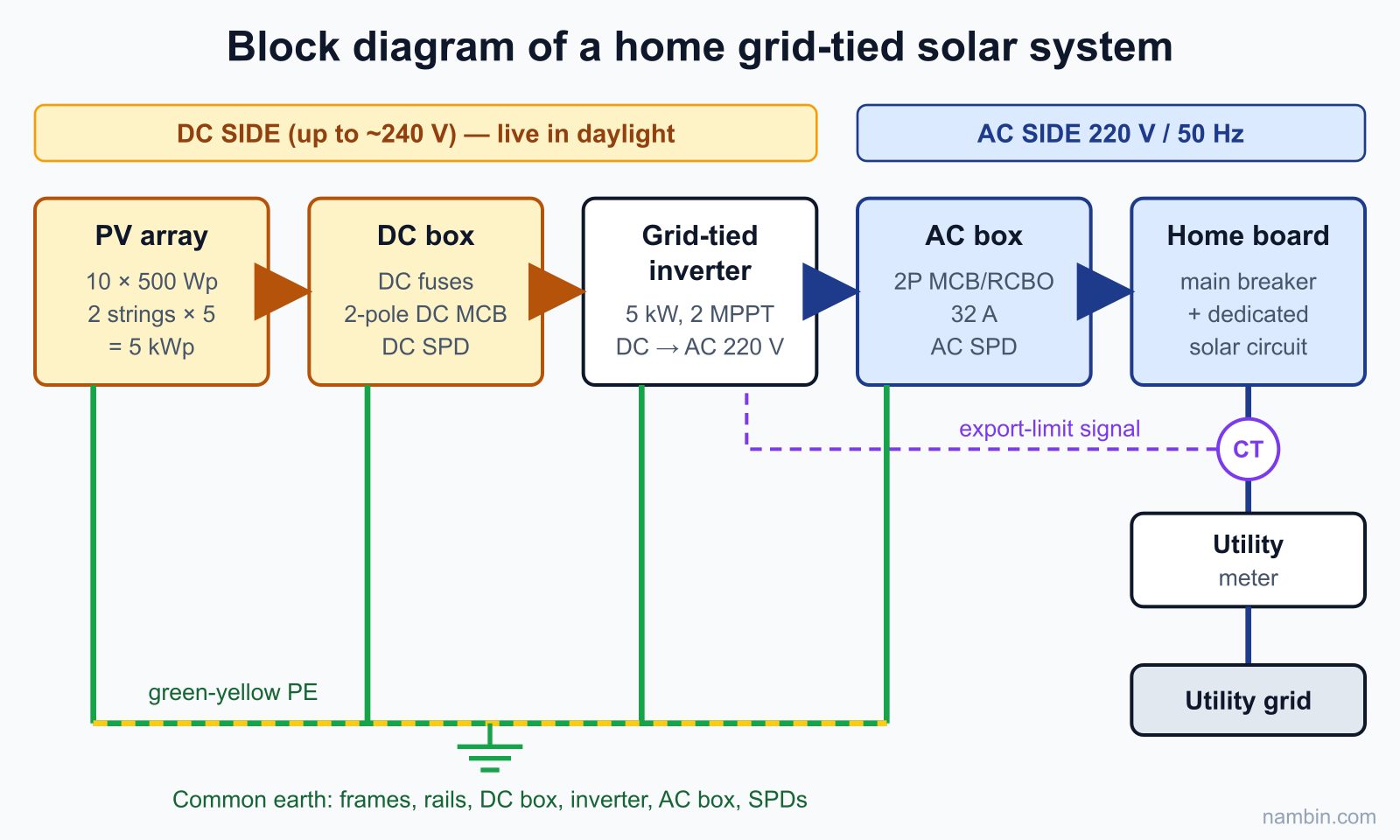
A grid-tied solar wiring diagram for a home runs in one direction: PV array → DC box (DC fuses, DC breaker, DC surge protector) → grid-tied inverter → AC box (MCB/RCBO, AC surge protector) → the home distribution board, downstream of the utility meter. Module frames, enclosures, the inverter casing and the surge protector terminals all share one earthing system. Everything before the inverter is high-voltage direct current that is live whenever the sun is up; everything after it is ordinary 220 V alternating current like any other household circuit.
Electricians are increasingly called to connect and maintain rooftop systems. This lesson helps you read the diagram, choose the devices and work safely on the DC side.
By the end of this lesson, you will be able to:
- Redraw the block diagram of a single-phase grid-tied system and point out exactly where the DC side ends and the AC side begins.
- List the devices in the DC box and the AC box, and explain why an ordinary AC breaker must never be used on a DC circuit.
- Check a string against the inverter and size the fuses, breakers and surge protectors for a 5 kWp system from the datasheets.
- Follow a safe shutdown and start-up sequence and avoid DC arcs when unplugging MC4 connectors.
- Explain export limiting to the homeowner and what to ask the local power company.
Want to take on rooftop solar installation and maintenance with confidence? The DC side, inverters, surge protection and commissioning are all practised and graded in the NAMBIN course Residential Electrician Level 3 – Master Electrician.
Which blocks make up a grid-tied solar wiring diagram?
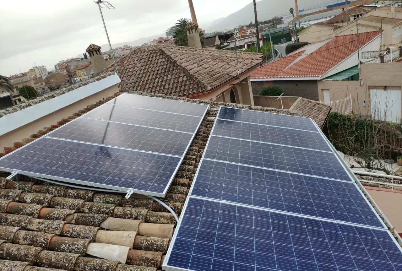
A grid-tied (on-grid) system has no battery. The inverter converts power from the panels into alternating current synchronised with the grid and feeds it straight to the loads in the house; any shortfall is drawn from the grid. Figure 1 shows the familiar layout: rows of panels on residential roofs.
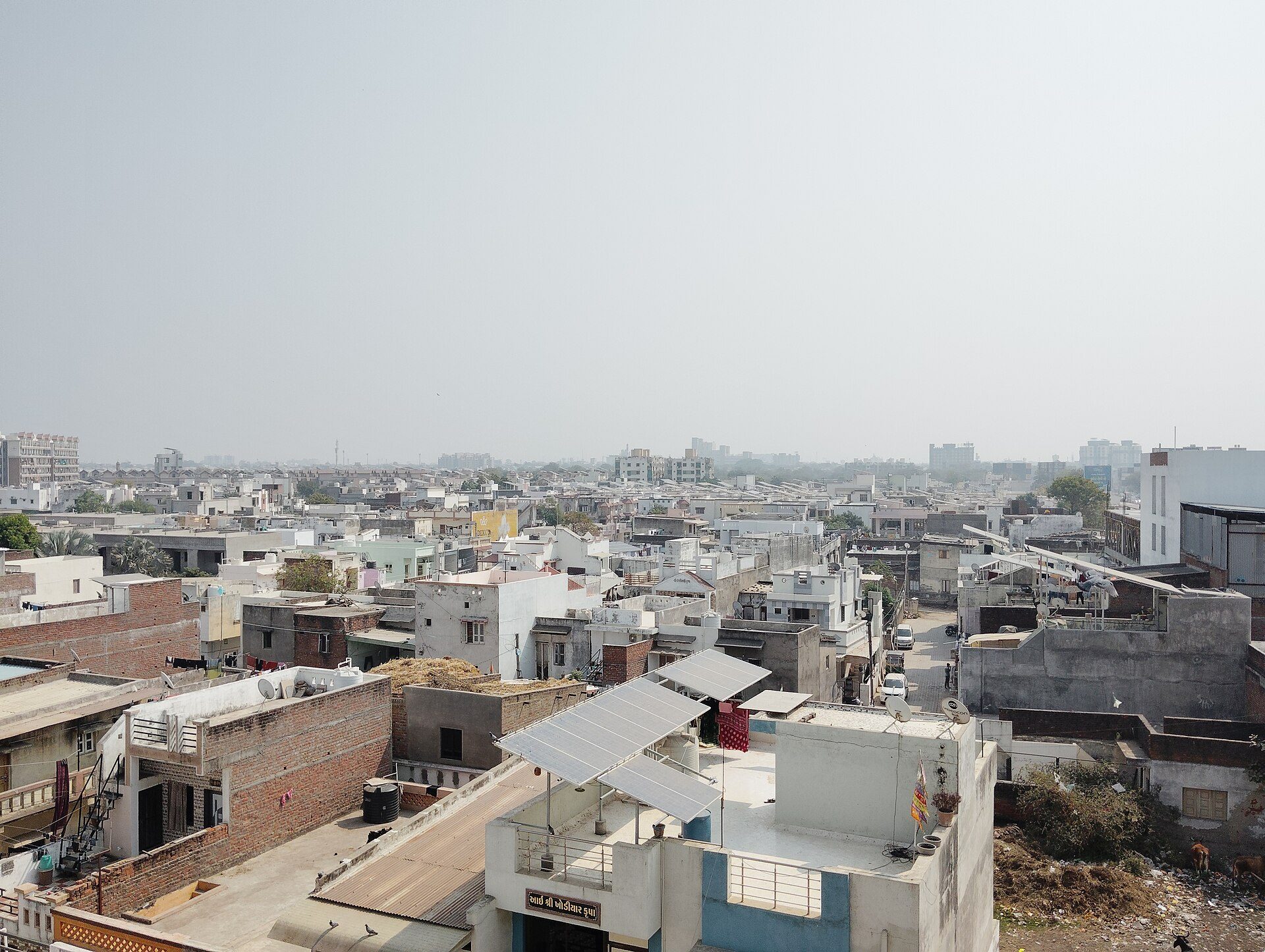
Photo: Nizil Shah / Wikimedia Commons, CC BY-SA 4.0
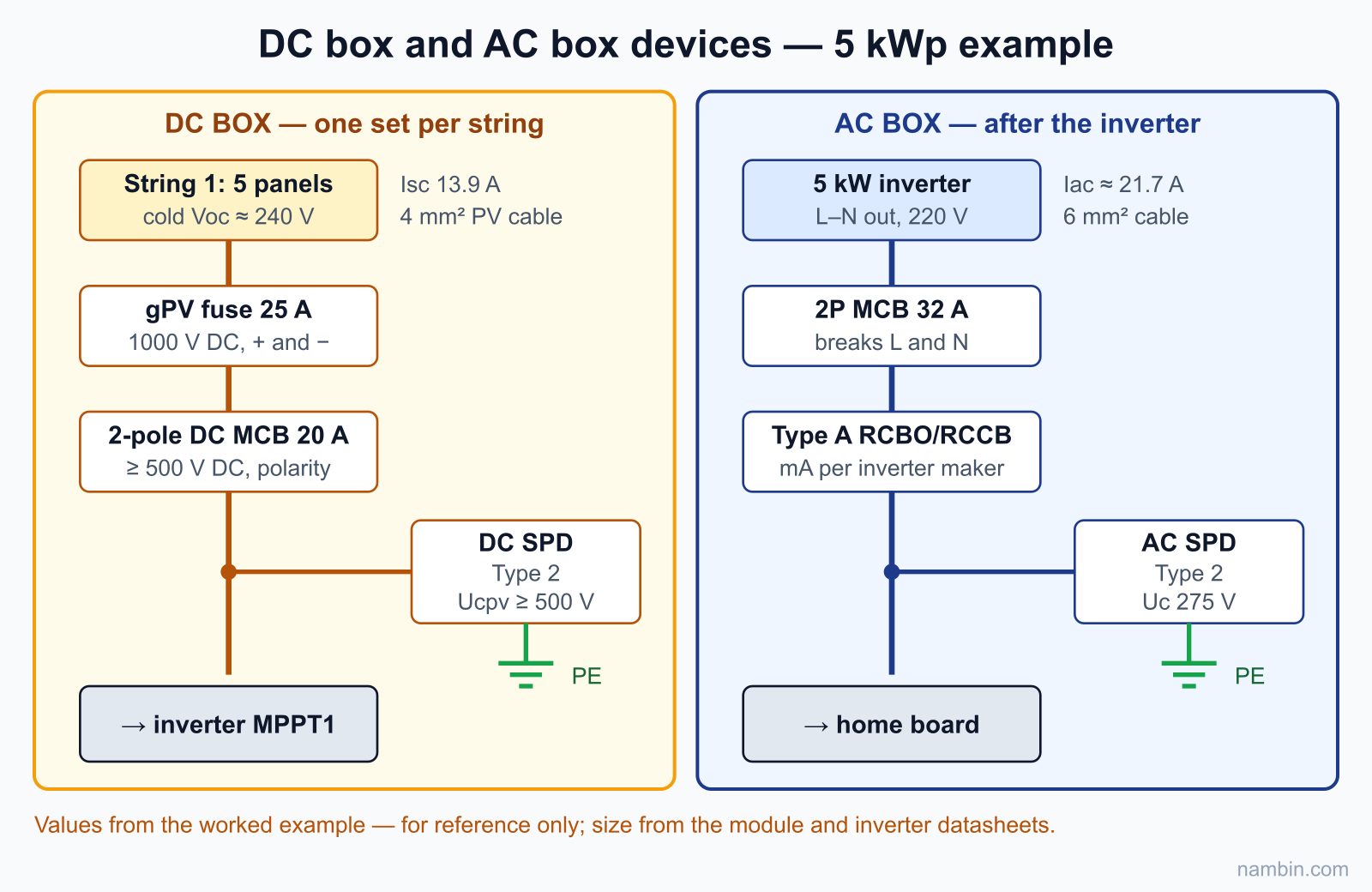
Figure 2 summarises the whole block diagram used as the example in this lesson: ten 500 Wp panels split into two strings and a 5 kW single-phase inverter with two maximum power point trackers (MPPTs).
The PV array and strings
Panels are connected in series to form a string: the positive lead of one panel plugs into the negative lead of the next using MC4 connectors. In series the voltages add up while the current stays equal to that of a single panel. Each string runs down to the DC box on two dedicated solar cables (PV cable, usually 4 mm² or 6 mm², with UV-resistant insulation).
What does a grid-tied inverter do?
The inverter does three jobs: it tracks the maximum power point of each string, converts DC into 220 V – 50 Hz AC synchronised with the grid, and disconnects itself when the grid goes down. That last function is called anti-islanding: during a power cut the inverter must not push energy into the line, so that utility crews repairing it are not put at risk. This is why a pure grid-tied system also shuts down during an outage, even in bright sunshine. Figure 3 shows a grid-tied inverter mounted on a wall in a home installation.
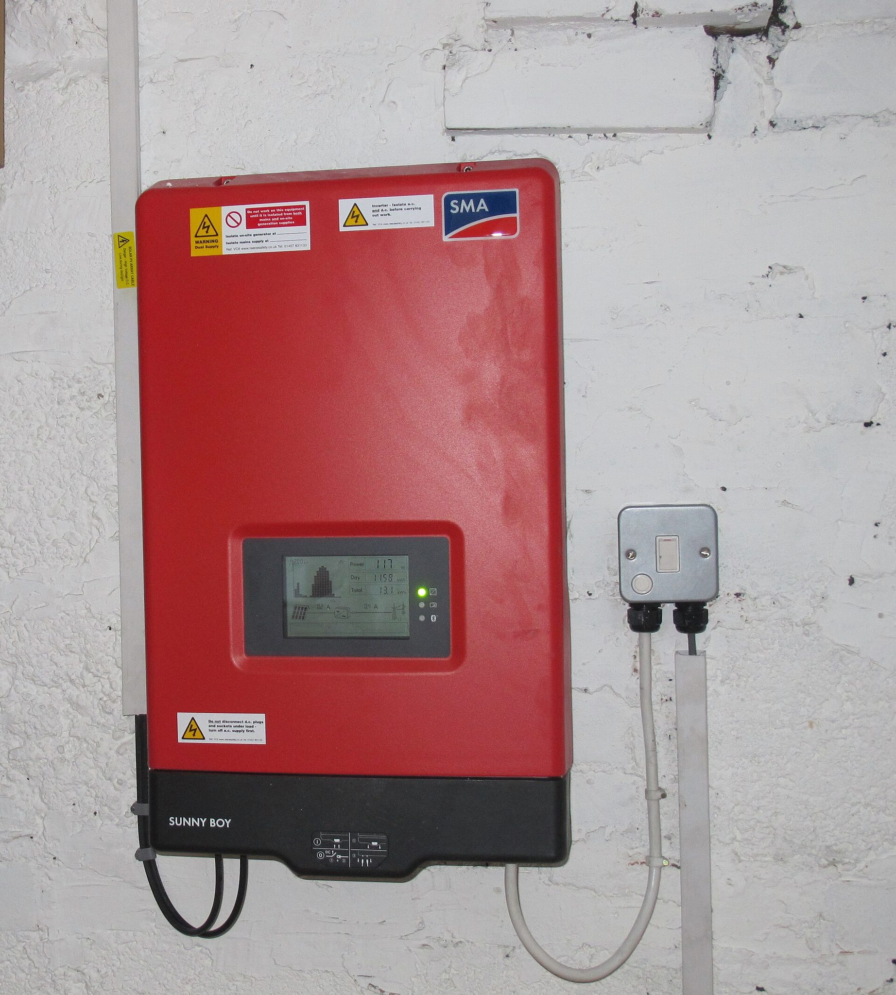
Photo: David Hawgood / Wikimedia Commons, CC BY-SA 2.0
Home board, meter and common earth
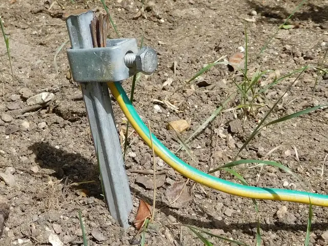
The output of the AC box connects to a dedicated circuit in the home distribution board, downstream of the meter and the main breaker. It looks like any load circuit, except that current flows the other way. Every metal part of the system (module frames, mounting rails, enclosures, the inverter casing, surge protector terminals) is bonded to a common earth bar with green-yellow PE conductors. For driving earth rods and measuring earth resistance, see the lesson installing a home distribution board: MCBs, RCBOs and safe earthing.
What goes inside the solar DC box and AC box?
The DC box sits between the array and the inverter, the AC box between the inverter and the home board. Many inverters include a DC switch and surge protection, but you still need to know the full set. The usual devices for a single-phase home system:
| Box | Device | Purpose | What to check when choosing |
|---|---|---|---|
| DC | DC fuse (gPV) and fuse holder | Protects cable and panels from reverse current fed by other strings | gPV type, DC voltage rating at least the system voltage (often 1000 V DC) |
| DC | 2-pole DC breaker or DC isolator | Switching and isolating a string for maintenance | Clearly marked "DC", high enough DC voltage rating, correct + / − polarity |
| DC | DC surge protective device (SPD, Type 2) | Diverts surges from nearby lightning to earth | Ucpv above the highest Voc of the string |
| AC | 2-pole MCB | Overload and short-circuit protection of the AC cable | Rating ≥ 1.25 × inverter output current |
| AC | RCBO/RCCB | Earth-leakage and shock protection | Type and sensitivity as specified by the inverter manufacturer |
| AC | AC surge protective device (Type 2) | Protects the inverter from grid-side surges | Uc 275 V for a 220 V single-phase supply |
DC box: fuses, DC breaker and DC surge protector
When three or more strings are connected in parallel, a faulty string receives reverse current from all the others, and the gPV fuse is there to interrupt it. In a small system where each string goes to its own MPPT, the risk of reverse current is low, yet many installers still fit fuses on both poles as an isolation point — follow the inverter manufacturer's instructions. Figure 4 shows a typical combiner box, where the fuses and DC surge protection are mounted.
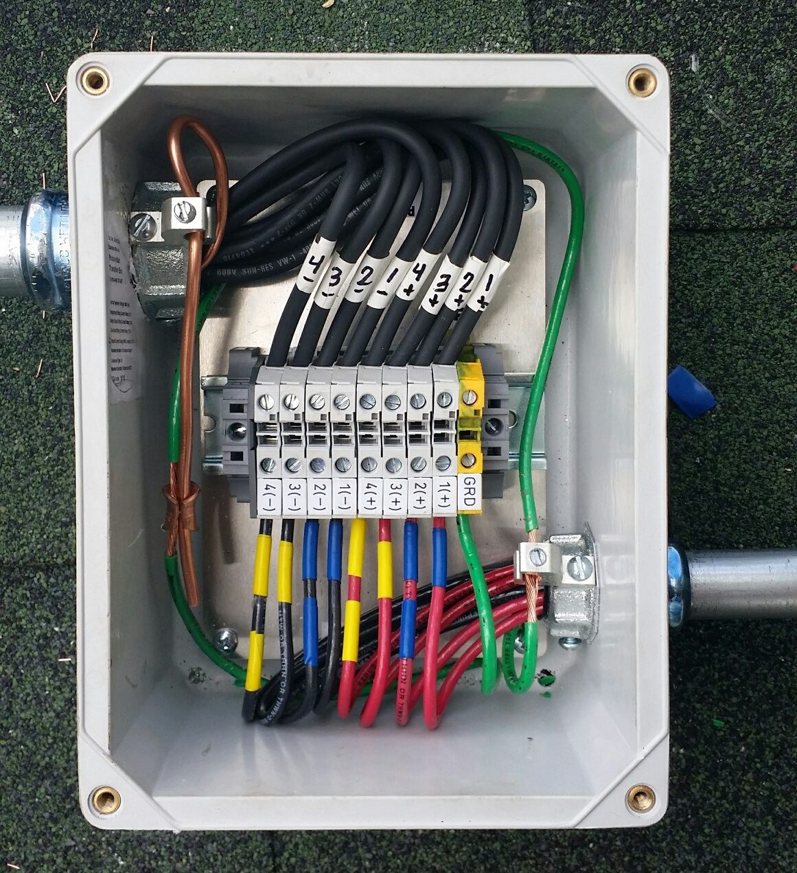
Photo: Ja.hess10 / Wikimedia Commons, CC BY-SA 4.0
AC box: MCB, RCBO and AC surge protector
The AC box is like a small sub-board: a 2-pole MCB breaking both L and N, an RCBO or RCCB for earth-leakage protection, and an AC surge protector connected in parallel between L, N and PE. Many inverters already monitor residual current internally; the manufacturer states whether an external device is needed, which type (usually Type A) and what sensitivity. Wiring the RCBO in and out and using its TEST button is exactly as described in how to wire an RCD (RCBO/RCCB) at home.
Why you must not use an AC breaker on a DC circuit
A 50 Hz current passes through zero a hundred times per second, so the arc dies out quickly; direct current never does. An AC breaker without a DC arc chute may fail to interrupt the current and set the enclosure on fire. Figure 5 details both boxes with the values from the 5 kWp example below.
The dangers of DC: what AC electricians tend to underestimate
The habit of "switch off the breaker and it is safe" does not hold on the DC side of a solar system.
⚠ Safety: Solar panels cannot be switched off while light falls on them — even under cloud, with every breaker open, the cables from the roof to the DC box still carry the full string voltage (around 230–240 V DC in this example). Never unplug an MC4 connector or open a fuse holder while current is flowing. Use only breakers, fuses and isolators rated for DC at the correct voltage and current. On the roof, wear a properly anchored safety harness and non-slip shoes, and never work on a wet roof or during a thunderstorm. Connection to the grid and the paperwork with the power company must be handled by a qualified contractor.
Light means voltage: no off switch at the source
A DC breaker only isolates what lies downstream of it; the cable between the panels and the breaker input is live all day. To work on that section, cover the panels completely with an opaque tarp and always measure the voltage before touching anything. In very dim light the current drops, but the open-circuit voltage stays close to its full value.
DC arcs and MC4 connectors
MC4 connectors (Figure 6) are designed to connect, not to interrupt current. Pulling an MC4 apart while the string carries 13 A creates a sustained DC arc that burns the connector and your hand. The most common cause of fires on the DC side is a badly crimped MC4 or a male and female from two different brands mated together: poor contact generates heat and, over time, melts the plastic. Always crimp with the correct dedicated tool, use a matched pair from the same manufacturer and give each joint a pull test.
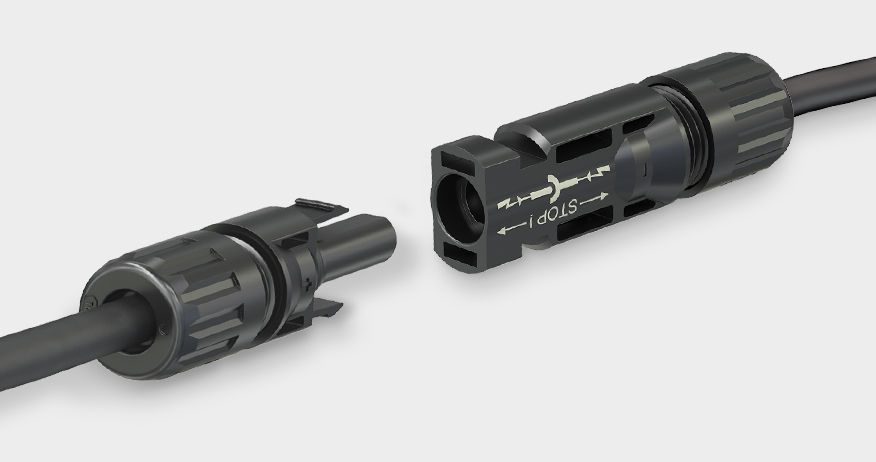
Photo: 2Inchs / Wikimedia Commons, CC BY-SA 4.0
Shutdown and start-up sequence
Follow the inverter manufacturer's manual; the usual sequence is:
- Open the AC breaker in the AC box → the inverter loses the grid, stops exporting, and the DC current falls to almost zero.
- Turn off the DC switch on the inverter (if fitted), then open the DC breaker in the DC box.
- Clamp each string cable with a DC clamp meter: it must read close to 0 A before you unplug any MC4 or open a fuse.
- Restart in reverse order: DC breaker, DC switch, and finally the AC breaker. The inverter checks the grid before it starts exporting, usually after a few tens of seconds to a few minutes.
Worked example: a 5 kWp system for a three-storey townhouse
The situation: a three-storey townhouse in Ho Chi Minh City with a south-facing metal roof with room for ten panels, and heavy daytime use (air conditioning, a shop freezer). The installer chooses ten 500 Wp panels and a 5 kW single-phase grid-tied inverter with two MPPTs. All figures below are reference examples only — always recalculate from the datasheets of the actual panels and inverter you install.
Step 1: split the strings and check the voltage
Panel datasheet (example): Voc 45.6 V; Vmp 38.2 V; Isc 13.9 A; Imp 13.1 A; Voc temperature coefficient −0.27 %/°C. Inverter datasheet (example): maximum DC voltage 550 V; MPPT range 80–520 V; maximum input current 16 A per MPPT, maximum short-circuit current 20 A.
- Two strings of five panels, one string per MPPT: 5 × 500 = 2,500 Wp per string, 5,000 Wp = 5 kWp in total.
- String Voc = 5 × 45.6 = 228 V. On a cold early morning, assume the cells are at 5 °C (20 °C below the 25 °C standard): Voc rises by 20 × 0.27 = 5.4 % → 228 × 1.054 ≈ 240 V, which is below 550 V → pass.
- String Vmp = 5 × 38.2 = 191 V, inside the 80–520 V window → pass.
- Current: Imp 13.1 A < 16 A and Isc 13.9 A < 20 A → pass.
Step 2: choose the DC box devices
- Fuse: at least 1.5 × Isc = 1.5 × 13.9 ≈ 20.9 A and no higher than the maximum series fuse rating printed on the panel (25 A in this example) → choose a 25 A gPV fuse rated 1000 V DC on both the + and − poles.
- DC breaker: current ≥ 1.25 × 13.9 ≈ 17.4 A → choose 20 A, 2-pole; DC voltage rating ≥ 1.2 × 240 ≈ 288 V → choose a model rated ≥ 500 V DC, wired with the polarity marked on its body.
- DC surge protector: Type 2, Ucpv comfortably above 240 V → a standard 500 V DC model.
- 4 mm² PV cable, 20 m from the roof to the box (40 m out and back): resistance ≈ 0.0175 × 40 / 4 = 0.175 Ω; voltage drop ≈ 13.1 × 0.175 ≈ 2.3 V, about 1.2 % of 191 V → pass (aim for under 1.5–2 %).
Step 3: choose the AC box devices and summarise
Inverter output current ≈ 5,000 W / 230 V ≈ 21.7 A (use the "maximum output current" in the datasheet if it is given). MCB ≥ 1.25 × 21.7 ≈ 27.2 A → choose a 2-pole 32 A MCB and 6 mm² copper cable for the 10 m run from the inverter to the home board. Summary:
| Item | Calculation | Choice (reference only, per datasheet) |
|---|---|---|
| Panels / strings | 10 × 500 Wp = 5 kWp | 2 strings × 5 panels, one MPPT each |
| Cold string Voc | 228 V × 1.054 ≈ 240 V | < 550 V inverter maximum |
| DC fuse | 1.5 × 13.9 ≈ 20.9 A | gPV 25 A – 1000 V DC, on + and − |
| DC breaker | 1.25 × 13.9 ≈ 17.4 A | 2-pole 20 A, ≥ 500 V DC |
| DC surge protector | Ucpv > 240 V | Type 2, 500 V DC |
| AC output current | 5,000 / 230 ≈ 21.7 A | 6 mm² cable |
| AC MCB | 1.25 × 21.7 ≈ 27.2 A | 2-pole 32 A |
| RCBO/RCCB | Per manufacturer | Type A, sensitivity per manufacturer |
| AC surge protector | 220 V single-phase supply | Type 2, Uc 275 V |
Reference yield in southern Vietnam is about 4 kWh per kWp per day: 5 × 4 = 20 kWh a day, roughly 600 kWh over a 30-day month; the north and the rainy season are lower.
Step-by-step connection procedure
Tools: a multimeter that reads at least 600 V DC, a DC clamp meter, an MC4 crimping tool and unlocking spanners, an earth resistance tester, a voltage tester, a safety harness and a tarp to cover the panels. Mounting the rails and panels on the roof is often done by a separate crew (Figure 7); the electrician is responsible for the connections and the tests.
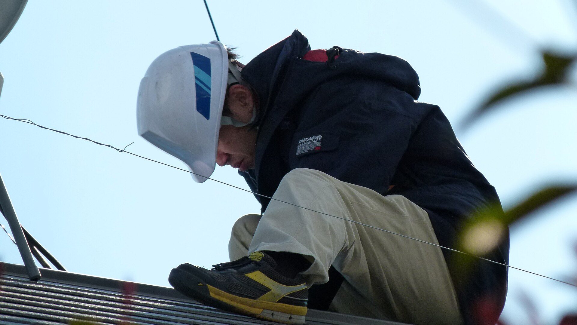
Photo: CoCreatr from Yokohama, Japan / Wikimedia Commons, CC BY-SA 2.0
DC side
- Connect the panels in series into strings and label both ends of each cable "string 1 +", "string 1 −" and so on. Do not plug them into the box yet.
- Measure the Voc of each string at the cable ends below the box: it should be close to the calculated value (about 220–240 V for five panels, depending on sunlight and temperature). A shortfall of one panel's worth (around 45 V) means a panel is wrongly connected or faulty.
- Check polarity with the meter: the red probe on the "+" cable must give a positive reading. Reversed polarity at the inverter can damage it.
- With the DC breaker and fuses open, connect the strings into the DC box and then into the correct MPPT inputs. Run the + and − cables close together in the same conduit to reduce induced lightning surges.
AC side and earthing
- Switch off the main breaker of the house and prove it dead. Fit a dedicated solar breaker in the home board and run the cable from the AC box.
- Connect L, N and PE by colour: brown or red for live, blue for neutral, green-yellow for earth — see electrical wire color codes: live, neutral and earth. On the DC side use red for "+" and black for "−" so they cannot be confused with AC conductors.
- Bond the panel frames, rails, enclosures, the inverter casing and the terminals of both surge protectors to the earth bar; measure the earth resistance — many installers require 4 Ω or less.
- Install the CT or smart meter for export limiting right after the utility meter, with the arrow on the CT pointing the correct way.
Test run and handover
Start up in the order given in the safety section and check the voltage on each MPPT and the output power in the inverter app. Press the RCBO TEST button and check the lugs for heat after 30 minutes in strong sun. Record the measured Voc values, the earth resistance and photos of the DC and AC boxes.
Export limiting (zero export) and dealing with the power company
When the household load is smaller than the solar output, a grid-tied system pushes the surplus through the meter into the grid — this is called exporting. Whether exporting is allowed, and whether it is paid for, depends on the rules in force at the time and on the agreement with the power company.
How does export limiting work?
A current transformer (CT) or smart meter installed just after the utility meter measures the direction of the current. As soon as power starts flowing out to the grid, it tells the inverter to reduce output to match the household load. A CT fitted backwards or in the wrong place (for example after a branch breaker) gives the inverter false readings, so it may keep exporting or produce far too little. After installation, switch off some loads at midday and check in the app that power to the grid drops to about zero.
Do you need permission from the power company?
In Vietnam, yes — at the very least you must notify, register or complete the procedure required by the local power company before connecting to the grid. The rules for rooftop solar in Vietnam have changed several times, so ask the power company in the area where you are installing about the current conditions. You will usually be asked for the panel and inverter capacity, a single-line diagram like Figure 5, the inverter certificates (anti-islanding, export limiting) and whether you intend to sell surplus power.
What should you remind the homeowner?
Do not connect to the grid before dealing with the power company (electronic meters record exported energy). Rented houses and shared roofs need the consent of the owner or building management; a weak roof needs a structural check. Keep the datasheets, the commissioning record and photos of the boxes.
Common mistakes when wiring a grid-tied solar system
1. An AC MCB used on a DC circuit
Symptom: the DC-side breaker runs hot, its casing turns black, sometimes the whole box burns. Cause: an ordinary breaker was bought instead of a DC breaker to save money. Fix: replace it with a DC breaker of the right voltage and polarity, and inspect the cables and base for heat damage.
2. Burnt, melted MC4 connectors
Symptom: a string's output drops and a connector is discoloured. Cause: crimped with ordinary pliers, mixed brands, nut not tightened. Fix: shut down in the correct sequence, cover the panels and re-crimp with matched connectors and the proper tool.
3. Inverter reports an insulation or leakage fault
Symptom: on damp mornings the inverter shows an insulation (ISO) fault. Cause: PV cable scraped on a metal roof edge, water in the DC box or an MC4. Fix: test each string's insulation to earth, find the damage and add conduit at the roof edge.
4. Surge protector without a proper earth
Symptom: the inverter fails after a storm even though surge protection was fitted. Cause: the SPD earth terminal was left unconnected, or the PE lead is long and looped. Fix: connect the SPD as a branch as in Figure 5, with a short, straight PE lead to the earth bar.
Practical exercise and self-assessment
The task: a system of eight 550 Wp panels (Voc 49.5 V; Isc 14.0 A; maximum series fuse 25 A) with a 4 kW inverter taking a single string, maximum DC voltage 550 V.
- Draw a block diagram like Figure 2 for this system. Pass if it includes the DC box, inverter, AC box, home board, meter and common earth, and marks the DC – AC boundary correctly.
- Calculate the string Voc and the Voc at 5 °C (8 × 49.5 = 396 V; × 1.054 ≈ 417 V). Pass if you correctly conclude that it is below 550 V.
- Choose the fuse and DC breaker (1.5 × 14.0 = 21 A → 25 A fuse; 1.25 × 14.0 = 17.5 A → 20 A breaker, ≥ 500 V DC). Fail if you pick an AC breaker or a DC breaker rated below 500 V.
- Describe the shutdown sequence before unplugging an MC4. Pass if you open the AC side first and confirm with a clamp meter that the DC current is close to 0 before unplugging.
Frequently asked questions
How many panels does a 5 kW home grid-tied system need?
Ten 500 Wp panels, or about nine 550 Wp panels (4.95 kWp); you need roughly 25–30 m² of roof. The string layout must be checked against the inverter datasheet, as in the worked example.
What goes inside a solar DC box and AC box?
DC box: gPV fuses, a DC breaker or DC isolator, a DC surge protector and an earth bar. AC box: a 2-pole MCB, an RCBO or RCCB as specified by the manufacturer, an AC surge protector and an earth bar. An outdoor enclosure should be rated IP65.
Do I need permission from the power company to install solar in Vietnam?
Yes. Before connecting to the grid you must notify or register with the local power company as it instructs. The rules change over time, so ask the power company where you are installing about the required documents and the current conditions for selling surplus power.
Will a grid-tied system give me power during a blackout?
No. A grid-tied inverter disconnects when the grid fails to protect line workers. For backup power you need a hybrid inverter with battery storage and a changeover arrangement for priority loads.
Summary and next steps
Remember three things: the diagram runs PV array → DC box → inverter → AC box → home board, all on a common earth; the DC side is live whenever it is light, so use only DC-rated devices; and connecting to the grid in Vietnam means dealing with the local power company first. This is the core of the roadmap step Rooftop solar, ATS and UPS; the next step is Smart home and low-voltage systems.
Ready to take on solar, ATS and UPS jobs on your own? String sizing, DC/AC boxes, surge protection, generator changeover and commissioning are taught step by step in the NAMBIN course Residential Electrician Level 3 – Master Electrician, with graded practical work and a certificate on completion.