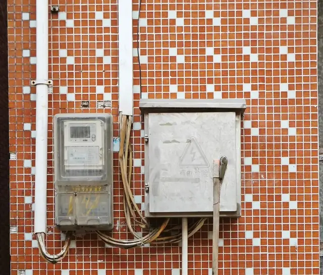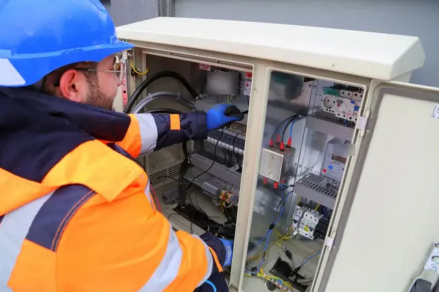
A client says the breaker for the kitchen "trips every evening", another wants to know whether the old cable to the water heater can take a new, bigger unit, and a third suspects the water pump is "eating electricity". In all three cases the question is the same: how much current is actually flowing? A clamp meter answers that in seconds, without cutting a wire or switching anything off.
This guide explains how a clamp meter works, how to choose one, and how to use it step by step on real residential jobs: measuring load current, checking a circuit against its breaker and cable, reading motor and appliance current, capturing starting (inrush) current, and the basics of hunting for leakage current.
Scope of this guide. This article is for trainee and working residential electricians on single-phase 230 V / 50 Hz supplies, as used in Vietnam. Clamping a conductor inside a distribution board means working near live parts. Only a competent person, using a meter rated for the location and following current Vietnamese regulations and the instrument manufacturer's instructions, should do it. Numbers marked for reference are typical values or worked examples; the nameplate of the actual appliance, the breaker rating and the cable data always come first.
How a clamp meter measures current
Every conductor carrying current is surrounded by a magnetic field whose strength is proportional to the current. The jaws of a clamp meter form a closed magnetic ring around the conductor and measure that field, so you never break into the circuit.
AC-only clamps work like a current transformer: the alternating field induces a small current in a coil inside the jaws. They are simple, robust and cheap, but they cannot see DC.
AC/DC clamps use a Hall-effect sensor that responds to steady fields too. You need one for solar panels, batteries and DC circuits. Before a DC reading you must press the zero (DCA zero / REL) button with the jaws closed and empty, because the sensor drifts and picks up the Earth's and nearby magnetic fields.
Leakage clamps have very sensitive jaws and a milliamp (mA) range. They are built to measure tiny differences in current, which an ordinary clamp cannot resolve.
The key consequence of this principle: the meter measures the net current through the jaws. If you clamp a cable with both line (L) and neutral (N) inside, the two currents flow in opposite directions, their fields cancel, and the meter shows almost zero even when a heater is running at full power. This is the single most common beginner mistake, and it is covered again in Step 3.
Parts of a clamp meter and what each one does
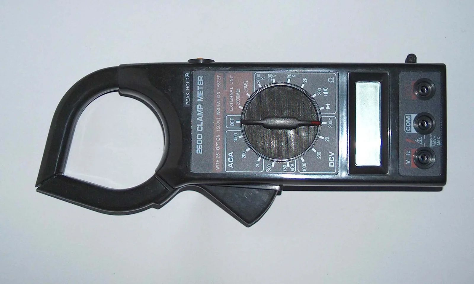
Figure 1. A digital clamp meter seen from the front: the open, curved jaws on the left, the trigger below them, a rotary function dial in the middle, the display, and the test lead sockets on the right. (Photo: Redecke, Wikimedia Commons, public domain)
Jaws with a trigger to open them. The maximum jaw opening limits the cable size you can clamp. The mating faces must be clean and close fully.
Rotary dial for function: A~ (AC current), A⎓ (DC current), V~, V⎓, Ω (resistance) and continuity on most models. Some meters also have a non-contact voltage (NCV) detector in the jaw tip.
Display and buttons: HOLD (freezes the reading), MAX/MIN, INRUSH, ZERO, and sometimes a Hz function.
Test lead sockets (COM and V/Ω) for voltage and resistance measurements. On most clamp meters current is measured only through the jaws, not through the leads.
Hand guard: the raised ridge between the jaws and the body. Your fingers stay behind it whenever the jaws are near a live conductor.
Choosing a clamp meter for residential work
You do not need the most expensive model, but a few features matter a lot for safety and accuracy:
Safety category (CAT) and voltage rating printed on the body, according to IEC 61010. For work inside a home distribution board, look for at least CAT III at a voltage above the supply voltage (for example CAT III 300 V or 600 V). CAT IV is the category for the origin of the installation, such as the incoming supply and the utility meter. A meter with no CAT marking does not belong anywhere near a distribution board.
True RMS. LED drivers, inverter air conditioners, phone chargers, computers and variable-speed pumps draw current in short peaks instead of a smooth sine wave. An "average-responding" meter can read such currents noticeably wrong; a True RMS meter reads them correctly.
Low-current resolution. Many general-purpose clamps resolve only 0.01 A or 0.1 A on their lowest range, which is fine for loads but useless for leakage. If leakage hunting is part of your work, a dedicated leakage clamp is the right tool.
Jaw size that fits the largest conductor you expect, such as the main incoming cable.
INRUSH and MAX/MIN functions for motors and loads that fluctuate.
AC/DC if you also work on solar or battery systems.
Step 1: Inspect the meter and prepare
Look over the case, jaws and test leads. Cracks, a jaw that does not close fully, exposed metal on the leads or a loose battery cover mean the meter is not used today.
Check the battery indicator. A weak battery can give wrong readings without any warning beyond a small symbol.
Read the CAT and voltage ratings and make sure they suit the place you will measure.
Wear dry, insulating footwear and keep your sleeves and any jewellery away from terminals. Use insulated gloves and eye protection when working inside an open board, as your company's procedure or the risk assessment requires.
Plan where you will clamp before opening anything. Often you can measure on an accessible single conductor (for example, the line wire leaving a breaker, or an extension cord through a line splitter) without removing any covers.
Step 2: Prove the meter on a known source
Before trusting a meter, prove it works. For the voltage function, measure a socket you know is live, then measure the circuit you are testing, then the known socket again (the "prove, test, prove" routine). For the current function, clamp a known load, such as a kettle or a heater whose nameplate power you know, through a line splitter, and check the reading is in the expected range.
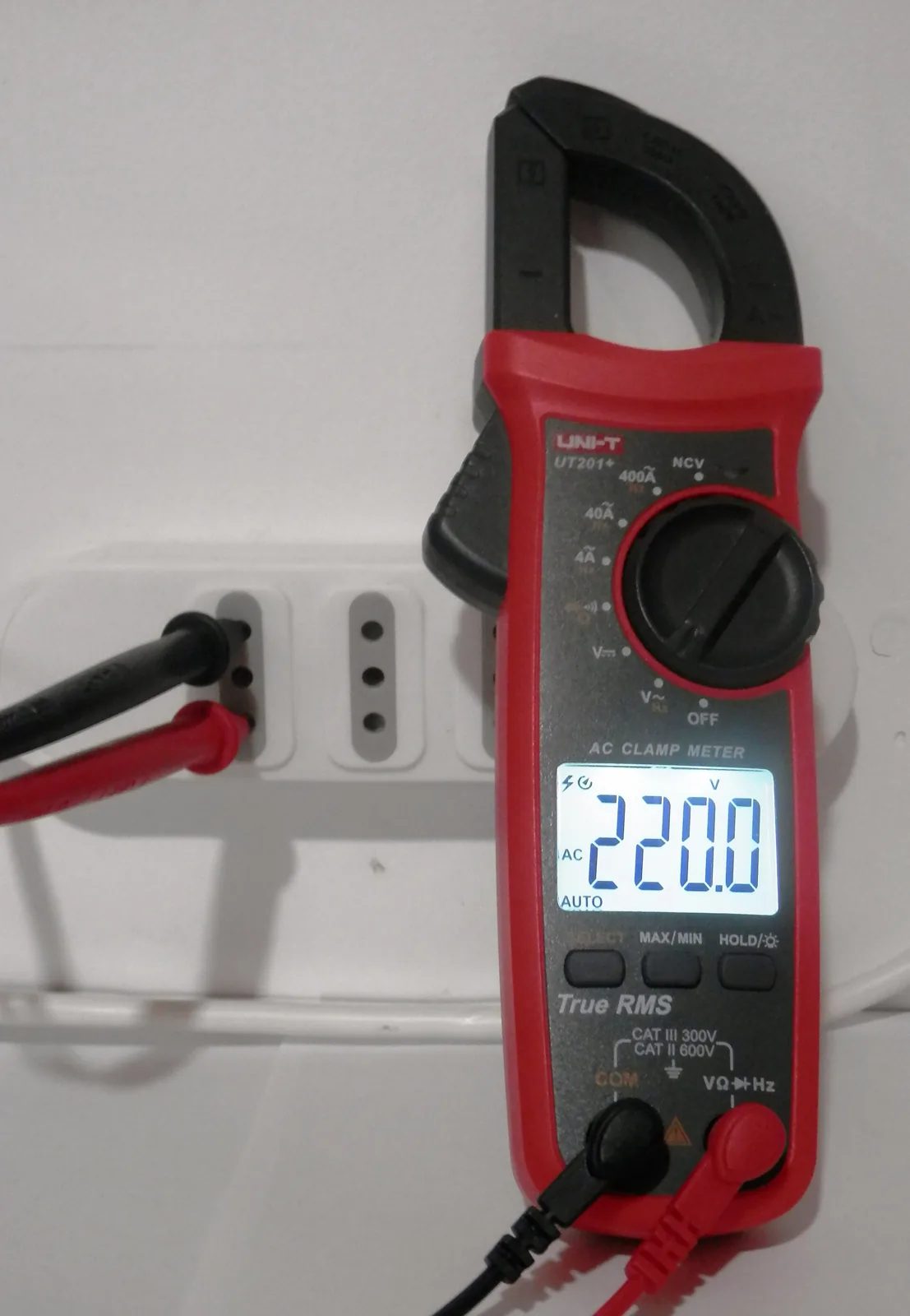
Figure 2. Proving the meter on a known live socket: a True RMS clamp meter set to AC voltage, with its red and black test leads plugged into a wall socket, shows 220.0 V on a 220 V / 50 Hz domestic supply. (Photo: Benjaminpvera, Wikimedia Commons, CC BY-SA 4.0)
Step 3: Clamp one conductor only
Set the dial to A~ (or A⎓ for DC, after zeroing), open the jaws and close them around one conductor only: the line wire, or the neutral wire, but never both together.
On an appliance cord or a sheathed cable, L and N sit side by side inside the same sheath, so you cannot clamp just one. Use a line splitter: a short adapter between plug and socket that separates the line conductor into a loop for the clamp. Many splitters also have a "×10" loop that multiplies the current ten times for small loads; divide the reading by ten.
Inside a board, clamp the individual line wire leaving the breaker, keeping the jaws away from bare terminals and busbars.
Centre the conductor in the jaws and keep them fully closed. A conductor pressed against one side, or a gap at the jaw tips, can reduce accuracy.
Keep other conductors away from the jaws. Strong fields from a nearby heavily loaded cable or a transformer can add error.
If the reading is around zero while the load is clearly running, the first thing to check is whether you have clamped L and N together.
Measuring very small currents
If a load draws only a few hundred milliamps and the meter cannot resolve it, you can wrap a single conductor several times through the jaws (for example with a short test lead in series, on a bench setup) and divide the reading by the number of turns. Five turns of a 0.2 A load read about 1.0 A. Do this only on a safe test arrangement, never by pulling installed wiring into loops.
Step 4: Read and record the current
Let the load reach normal operation. A water heater element draws steady current; a fridge compressor cycles on and off; a washing machine changes with each stage.
Use HOLD if you cannot see the display while clamping, then remove the meter before reading it.
For loads that change, use MAX/MIN and leave the clamp on for a few cycles.
Write down the reading, the circuit, the breaker rating, the cable size if known, and what was running at the time. A reading without context is not useful a week later.
From current to power: a quick check
For resistive loads (water heater elements, kettles, irons, incandescent or heating elements), power is approximately voltage × current. On a 230 V supply:
A 2,500 W water heater draws about 2,500 ÷ 230 ≈ 10.9 A.
A 2,000 W kettle draws about 2,000 ÷ 230 ≈ 8.7 A.
For motors, compressors and electronic loads, real power is lower than V × I because of the power factor, so do not use this formula to estimate an electricity bill for those loads; compare with the nameplate current instead. If the measured voltage is well below 230 V, the current of a resistive load will also be lower than calculated.
Step 5: Check a circuit against its breaker and cable
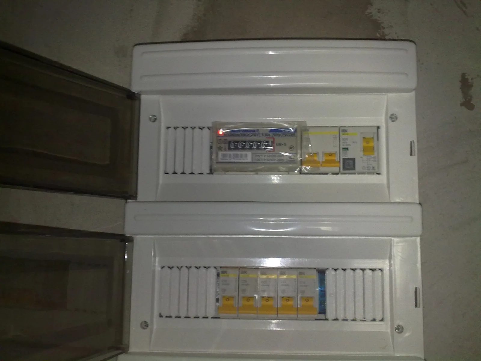
Figure 3. A small home distribution board with its doors open: an electricity meter and main devices in the upper row and five miniature circuit breakers in the lower row. Read each breaker's rating before comparing it with the current you measure on its circuit. (Photo: Сизарев Евгений, Wikimedia Commons, CC BY-SA 3.0)
This is the job behind "the breaker trips every evening" and "can I add another air conditioner to this circuit?".
Read the breaker rating printed on the MCB (for example C16, C20, C32) and identify the cable size of the circuit if you can see it.
Switch on the loads that the client normally runs together at the busiest time: in a kitchen that might be the induction hob, the kettle and the rice cooker together.
Clamp the line conductor of that circuit and record the steady current and the MAX value.
Compare. If the measured current regularly approaches or exceeds the breaker rating, the trips are overload trips, not a faulty breaker. Typical remedies are spreading loads across circuits or running a dedicated circuit for a large appliance, with cable and breaker sized correctly for it. If the current is well below the rating but the breaker still trips, suspect something else: a short circuit, a loose connection heating the breaker, a weak breaker, or, if it is an RCD or RCBO that trips, leakage current rather than overload.
Check the cable, not only the breaker. The breaker must protect the cable. If someone has fitted a larger breaker on a small cable to "stop the tripping", the cable can overheat without the breaker ever tripping. That is a dangerous fault to report, not a fix.
Clamp the main incoming line conductor (if accessible and your meter is rated for it) to see the total load of the house against the main breaker.
Comparing line and neutral current
On a healthy single-phase circuit, the current in the line conductor and in its own neutral conductor should be practically the same. If they differ noticeably, some current is returning another way: through the earth (a leakage fault) or through a neutral shared with another circuit (a "borrowed neutral" wiring error). Both explain many unexplained RCD trips.
Step 6: Measure motor and starting (inrush) current
Motors in water pumps, fridge and air conditioner compressors, and washing machines draw a short surge of current when they start, often several times their running current, before settling. A standard reading is too slow to catch it.
Select the INRUSH function (sometimes a long press on a button; check your manual).
Clamp the line conductor of the motor circuit with the motor off.
Start the motor. The meter captures the peak of the starting surge.
Then switch to normal A~ and record the running current.
Compare the running current with the motor's nameplate current (often marked "A" or "FLA"). A running current clearly above the nameplate can point to a mechanical load problem (a seized bearing, a blocked impeller, a pump running against a closed valve) or low supply voltage. A single-phase motor that hums, draws high current and does not start often has a failed start capacitor, which you can then test with the multimeter's capacitance function after isolating and discharging it.
Inrush figures explain why a pump trips a small breaker only when it starts, and help you choose a breaker with a suitable tripping curve. Follow the motor and breaker manufacturers' guidance rather than guessing.
Step 7: The basics of leakage current checks
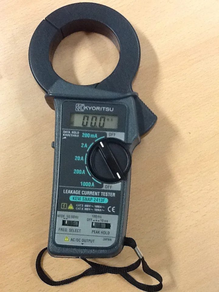
Figure 4. A leakage current clamp tester with large jaws and ranges from 200 mA up to 1000 A on its dial, plus a frequency filter and peak-hold switches. The milliamp range is what lets it measure leakage, which an ordinary clamp cannot resolve. (Photo: balurbala, Wikimedia Commons, CC BY-SA 3.0)
An RCD or RCBO trips when it detects a difference between the current going out on line and returning on neutral. You can use the same principle with a clamp.
Clamp line and neutral together (all live conductors of the circuit). Now the normal load currents cancel, and what remains is the current returning some other way, typically through the earth conductor: the leakage current.
Alternatively, clamp the circuit's earth conductor on its own to see current flowing to earth.
These measurements need a meter with a milliamp range, which in practice means a leakage clamp. A 30 mA RCD is designed to trip at a residual current somewhere between half its rating and its full rating, so leakage of a few milliamps is significant. An ordinary 0.01 A-resolution clamp shows "0.00" for leakage that may already be causing nuisance trips.
A practical leakage hunt in a home:
With a leakage clamp around L and N of the whole installation (at the main tails or below the RCD), note the total leakage.
Clamp each outgoing circuit's L and N together in turn to find the circuit with the most leakage.
On that circuit, unplug or switch off appliances one at a time and watch the reading fall. A water heater element, a washing machine, outdoor lighting or a damp junction box are common culprits.
Confirm the faulty item with an insulation resistance test once it is isolated, and repair or replace it.
Some leakage is normal: many electronic appliances have filters that let a small current flow to earth. What matters is the total across a circuit protected by one RCD, and sudden changes. If an RCD keeps tripping, the cause must be found; never bypass or remove an RCD to stop the trips.
Reference table: common readings and what they mean
Where you clamp | What you might see (for reference) | What it usually means |
|---|---|---|
Line wire of a 2,500 W water heater circuit, heater on | About 10 to 11 A at 230 V | Normal for a resistive load of that power |
Whole appliance cord (L and N together) | About 0 A while the appliance runs | Fields cancel; use a line splitter |
Line wire of a circuit at peak use | Close to or above the MCB rating | Overload; spread loads or add a dedicated circuit |
Line wire, breaker trips but current is low | Well below the MCB rating | Look for a short circuit, loose connection, faulty breaker, or leakage if it is an RCD/RCBO |
Line and neutral of one circuit, separately | Noticeably different currents | Leakage to earth or a neutral shared with another circuit |
Line and neutral together, leakage clamp | A few mA, rising when one appliance is on | That appliance or its wiring is leaking; test its insulation |
Motor circuit, INRUSH mode | A short peak several times the running current | Normal starting surge; size protection accordingly |
Motor running current | Clearly above the nameplate current | Mechanical overload, low voltage or a failing motor/capacitor |
DC circuit, reading drifts with nothing clamped | A small non-zero value | Hall sensor offset; press ZERO before measuring |
The values above are examples for understanding. Always compare against the actual nameplate, breaker rating and cable data on the job.
Common mistakes and how to avoid them
Clamping a whole cable. Reads near zero. Separate one conductor or use a line splitter.
Using the current function through the test leads. On most clamp meters the leads are for voltage and resistance only. Never connect the leads in series with a circuit unless the manual explicitly supports it on that range.
Measuring voltage while the dial is on resistance or continuity. Always check the dial before touching the probes to a live part.
Forgetting to zero for DC. The reading can be off by a noticeable amount.
Trusting a non-True-RMS reading on electronic loads. Inverter appliances and LED lighting can be misread.
Fingers past the hand guard or the jaw tips knocking against a busbar or bare terminal. Clamp slowly, look where the tips go, and keep the other hand away from the board.
Writing down a number without conditions. Always note what was running.
Explaining the results to the client
Clients rarely care about amps; they care about whether something is safe and what it will cost them. Translate your readings:
"With the hob, kettle and rice cooker on together, this circuit draws about the same as the breaker's limit, which is why it trips in the evening. The breaker is doing its job. The safe fix is a separate circuit for the hob."
"Your pump draws far more current than its label says when running, so it is working hard; the bearing or impeller should be checked before the motor burns out."
"We found leakage current on the bathroom circuit that goes away when the water heater is unplugged. The heater needs testing or replacing."
Write the readings in your job report. It shows the client you measured rather than guessed, and it gives you a baseline if they call you back.
Safety checklist
☐ Meter, jaws and leads inspected; no cracks or damage; battery not low.
☐ CAT and voltage rating suitable for the measurement location (at least CAT III for a distribution board).
☐ Meter proved on a known source before use.
☐ Dry hands and insulating footwear; PPE as required when an enclosure is open.
☐ Covers removed only if necessary and only by a competent person; bare parts identified before reaching in.
☐ Fingers behind the hand guard; jaw tips kept clear of bare terminals and busbars.
☐ One conductor clamped at a time for load current; correct function selected on the dial.
☐ Correct function selected before connecting test leads for voltage.
☐ No breaker upsized and no RCD bypassed to "solve" a problem.
☐ Covers refitted and the board left closed and safe; readings recorded.
Frequently Asked Questions
Why does my clamp meter read zero on a running appliance?
You have almost certainly clamped the whole cord, with line and neutral inside the jaws. Their currents are equal and opposite, so the magnetic fields cancel. Clamp a single conductor, or use a line splitter between the plug and the socket.
Can a clamp meter measure DC current from solar panels or batteries?
Only if it is an AC/DC (Hall-effect) model. An AC-only clamp will show nothing or a meaningless value on DC. With an AC/DC clamp, press the ZERO button with the jaws closed and empty right before measuring.
Do I need a True RMS clamp meter?
For modern homes, yes, if you can. LED lighting, inverter air conditioners, computers and variable-speed pumps draw distorted current that an average-responding meter may misread. For purely resistive loads such as a water heater element, both types read similarly.
Can I find what is tripping my RCD with an ordinary clamp meter?
Usually not. RCD trips are caused by leakage currents in the milliamp range, below the resolution of most general-purpose clamps. A leakage clamp with a mA range, used around line and neutral together, is the proper tool, followed by an insulation resistance test on the suspect appliance or circuit.
Is it safe to use a clamp meter inside a live distribution board?
It can be done safely by a competent person with a properly rated meter (CAT III or higher for the voltage), suitable PPE and care to keep the jaws away from bare parts. If you are a trainee, do it only under supervision. Whenever an accessible conductor outside the board will do, measure there instead.
How accurate is a clamp meter?
Accuracy depends on the model and range and is given in the manual as a percentage of the reading plus a number of digits. It is usually best when the conductor is centred, the jaws are clean and closed, and the current is well within the selected range. Readings near the bottom of a range are less accurate.
What is the difference between a clamp meter and a multimeter?
A multimeter measures current only when connected in series with the circuit, which means disconnecting a wire, and usually only up to about 10 A. A clamp meter measures current without breaking the circuit and handles much larger currents. Many clamp meters also measure voltage and resistance, but a good multimeter is usually better for low-level electronic measurements.
Practice Exercises
Cancel-out demonstration. On a bench, run a kettle through a line splitter. Clamp the single-conductor loop and record the current, then clamp the whole cord. Explain the difference in one sentence.
Power check. Read the nameplate power of three resistive appliances (kettle, iron, heater), calculate the expected current at your measured voltage, then measure it with the clamp through a line splitter. Compare and explain any difference.
Small-current trick. On a safe bench setup, measure a small load once with one turn and once with five turns through the jaws. Divide the second reading by five and compare.
Circuit loading survey. Under supervision, in a home or training board, record the breaker rating, cable size and peak current for every circuit while typical loads run. Mark any circuit above about 80% of its breaker rating for review (80% is a practical working threshold for this exercise, not a standard).
Inrush capture. Using INRUSH mode, record the starting peak and running current of a small pump or fan, and compare the running current with its nameplate.
Client explanation. Write three short sentences, in plain language, explaining your survey results to a homeowner who has no electrical knowledge.
A clamp meter turns guesses into numbers. Learn to clamp one conductor, read with context, and compare against the breaker, the cable and the nameplate, and you will solve most "mystery" tripping and overheating complaints faster and more safely.